English
 Español

 Inquiry
Connecting a fiber optic cable means joining two fiber ends so light signals can pass from one segment to another with the lowest possible loss. This process—whether done by fusion splicing, mechanical splicing, or using factory‑terminated connectors—directly determines the reliability and speed of a network. This guide shows how to connect fiber cable correctly, from tool selection to final testing, with concrete data and field‑proven methods.
Content
- 1 What You Need to Know Before Connecting Fiber Cable
- 2 Step-by-Step: How to Connect Fiber Cable in 7 Stages
- 2.1 1. Gather the Right Tools and Safety Gear
- 2.2 2. Strip the Cable Jacket and Buffer Properly
- 2.3 3. Clean the Fiber End‑Face Thoroughly
- 2.4 4. Cleave the Fiber for a Perfect Flat End
- 2.5 5. Choose Your Connection Method: Fusion Splicing, Mechanical Splicing, or Pre‑Polished Connectors
- 2.6 6. Perform the Splice or Connector Attachment
- 2.7 7. Test the Connection with an OTDR or Light Source and Power Meter
- 3 Detailed Comparison: Fusion Splicing vs. Mechanical Splicing vs. Pre‑Polished Connectors
- 4 Common Mistakes That Increase Signal Loss
- 5 Frequently Asked Questions About Connecting Fiber Cables
- 6 Final Tips for a Reliable Fiber Connection
What You Need to Know Before Connecting Fiber Cable
Every connection starts with choosing the right fiber type and connector interface. The two fundamental categories are single‑mode and multimode fiber. Single‑mode uses a 9‑micron core and carries one light path, making it suitable for distances up to 80 km or more. Multimode typically has a 50‑micron core (OM3, OM4, OM5) and supports multiple light paths over shorter distances, usually within a data center or campus. According to the ITU‑T G.652 standard, a standard single‑mode fiber exhibits attenuation of no more than 0.4 dB/km at 1310 nm and 0.3 dB/km at 1550 nm. In contrast, OM4 multimode fiber has a maximum attenuation of 3.0 dB/km at 850 nm, as specified by ISO/IEC 11801. Picking the wrong fiber for the job instantly adds unnecessary loss before any connection is made.
Single-Mode vs. Multimode Fiber – A Quick Comparison
| Feature | Single‑Mode (OS2) | Multimode (OM4) |
|---|---|---|
| Core Diameter | 9 µm | 50 µm |
| Typical Wavelength | 1310 nm / 1550 nm | 850 nm / 1300 nm |
| Max Attenuation (per km) | 0.4 dB (1310 nm) | 3.0 dB (850 nm) |
| Recommended Distance | Up to 80 km without regeneration | Up to 400 m (100G SR4) |
| Cost of Transceivers | Moderate to high | Lower |
Table: Optical characteristics of commonly used single‑mode and multimode fibers. Data sources: ITU‑T G.652 and ISO/IEC 11801.
Common Fiber Connector Types
The connector interface determines physical compatibility and insertion loss performance. The four most encountered connectors in the field are LC, SC, ST, and FC. LC connectors dominate high‑density data centers because their 1.25 mm ferrule allows 48 or more ports in a single rack unit. SC connectors, with a 2.5 mm ferrule, remain popular in access networks for their push‑pull ease. ST uses a bayonet‑style twist lock and is still found in older campus backbones. FC connectors, with a threaded coupling, are occasionally used in test equipment and high‑vibration environments.
| Connector | Ferrule Size | Typical Insertion Loss | Common Use |
|---|---|---|---|
| LC | 1.25 mm | ≤ 0.15 dB (premium) | Data centers, SFP modules |
| SC | 2.5 mm | ≤ 0.20 dB | FTTH, patch panels |
| ST | 2.5 mm | ≤ 0.30 dB | Legacy LAN, security cameras |
| FC | 2.5 mm | ≤ 0.30 dB | Test instruments, high‑vibration |
Table: Common fiber connector types and their typical insertion loss as defined by IEC 61753-1 performance grades.
Step-by-Step: How to Connect Fiber Cable in 7 Stages
A reliable fiber connection follows a strict sequence: prepare, strip, clean, cleave, join, protect, and test. Each stage removes a potential source of signal loss. The following steps apply whether you are splicing two bare fibers or attaching a pre‑polished connector in the field.
Remove jacket & buffer
Wipe end‑face
Flat perpendicular end
Core alignment
Fuse or lock
Sleeve or housing
Verify loss
1. Gather the Right Tools and Safety Gear
A complete tool kit eliminates improvisation that leads to high loss. At a minimum, you need a fiber stripper (with precise 125 µm cladding capability), a cleaver, a fiber optic cleaning kit (one‑click cleaner for connectors, lint‑free wipes and 99% isopropyl alcohol for bare fiber), a visual fault locator (VFL), an optical power meter and light source, and the splicing or connector system you intend to use. For fusion splicing, a fusion splicer with active core alignment can achieve average splice loss of 0.02 dB, while a basic clad‑alignment splicer averages around 0.05 dB, according to multiple manufacturer data sheets. Always wear safety glasses with side shields, and never look directly into a fiber end that may carry live light. Dispose of fiber scraps in a sealed container immediately because glass shards are a skin‑puncture hazard.
2. Strip the Cable Jacket and Buffer Properly
Clean stripping preserves the bare glass’s mechanical strength. For a standard 900 µm tight‑buffered fiber, start by removing the outer jacket with a jacket stripper, exposing the buffer. Then use a buffer stripper set to exactly the coating diameter (typically 250 µm) to peel away the coating without nicking the cladding. A single nick deeper than 1 µm creates a stress concentration point that will eventually cause the fiber to break under thermal cycling. Field data from the Fiber Broadband Association shows that 12% of network outages traced to fiber breaks originated from mechanical damage during stripping. After stripping, wipe the bare fiber with a lint‑free wipe moistened with isopropyl alcohol to remove coating debris.
3. Clean the Fiber End‑Face Thoroughly
Contamination is the single largest cause of connector‑related insertion loss and reflectance failure. A single dust particle of 1 µm diameter can block a significant portion of a 9 µm single‑mode core. Inspection with a 200x or 400x fiber scope is essential; the IEC 61300-3-35 standard defines four zones on the end‑face and sets pass/fail limits for scratches and defects. For a single‑mode PC connector, Zone A (the core) must have no defects larger than 2 µm. Cleaning must follow a wet‑dry protocol: wipe with an alcohol‑dampened wipe, then immediately with a dry wipe, moving in one direction only to avoid re‑depositing debris. Automated one‑click cleaners for bulkhead adapters reduce contamination risk to less than 0.5% of connections when used correctly.
4. Cleave the Fiber for a Perfect Flat End
A high‑quality cleave produces a mirror‑smooth end face perpendicular to the fiber axis. Even a 1° cleave angle can add 0.5 dB or more to a mechanical splice. The cleaver scribes a tiny scratch on the glass under controlled tension, causing a clean fracture. Cleave quality is influenced by how well the fiber is clamped and the sharpness of the diamond blade. A blade typically delivers 30,000 to 50,000 cleaves before replacement. In field splicing, a cleave angle below 0.5° is the target for fusion splicing. For mechanical splicing and pre‑polished connectors, angles up to 1.5° may still work, but loss will increase. Always place the cleaver on a stable, vibration‑free surface.
5. Choose Your Connection Method: Fusion Splicing, Mechanical Splicing, or Pre‑Polished Connectors
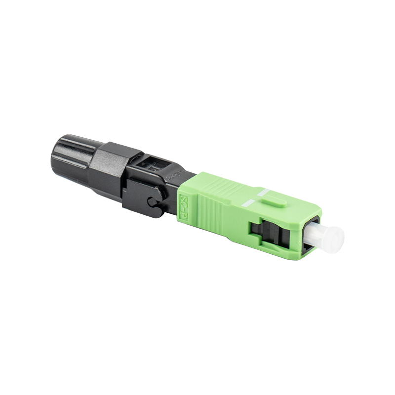
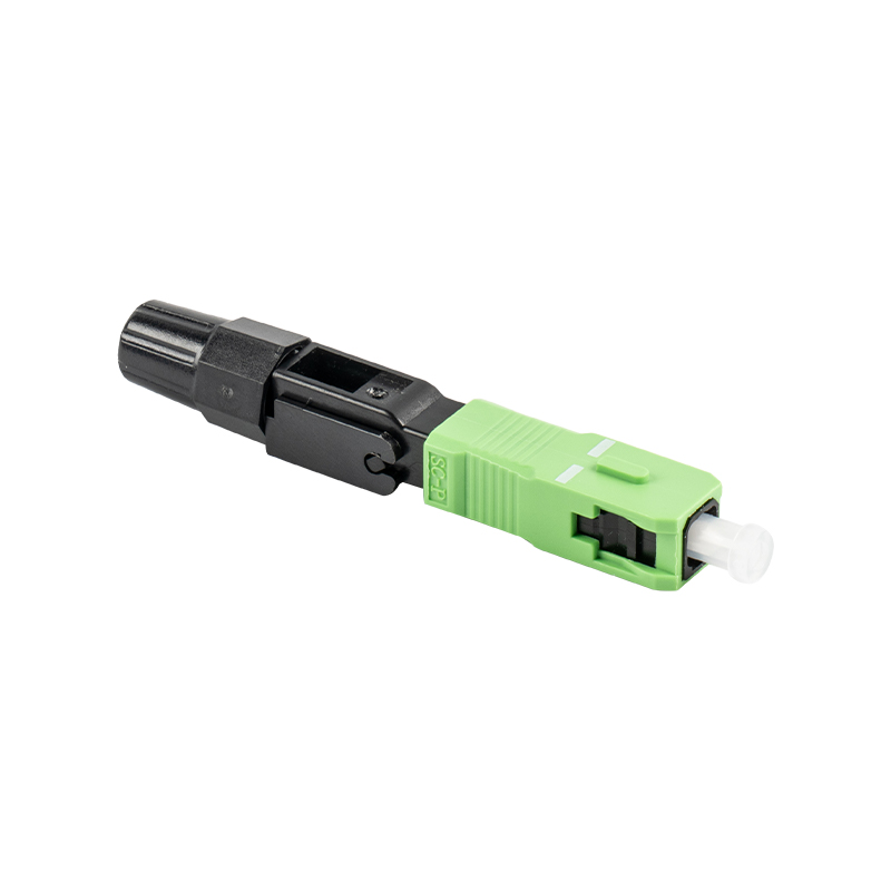
The connection method dictates long‑term reliability and insertion loss budget. Three methods dominate field installations. Fusion splicing welds two bare fibers together using an electric arc, producing the lowest loss and a permanent joint. Mechanical splicing aligns two fibers inside a precision V‑groove and holds them with index‑matching gel; it is faster but typically has higher loss and less mechanical strength. Pre‑polished field‑installable connectors let you terminate a fiber directly with a connector that already has a polished ferrule and a stub fiber inside; you cleave the field fiber, insert it into the connector, and lock it mechanically or with a cam. Each approach fits a specific scenario.
Fusion Splicing
- Average splice loss: 0.02–0.05 dB
- Permanent, high‑strength joint
- Requires expensive splicer machine
- Typical per‑splice time: 2–4 minutes
Mechanical Splice
- Typical insertion loss: 0.1–0.3 dB
- No power needed for assembly
- Low tool cost, gel can dry out
- Assembly time: 1–2 minutes
Pre‑Polished Connector
- Insertion loss: 0.15–0.5 dB
- No splicing machine required
- Quick field termination
- Re‑usable on some models
6. Perform the Splice or Connector Attachment
Execute the join according to the manufacturer’s specifications to hit low‑loss targets. For fusion splicing, place the prepared fibers in the splicer’s V‑grooves, close the electrodes, and let the machine auto‑align the cores. Modern core‑alignment splicers evaluate the core position using image profile analysis and apply an arc discharge that typically lasts 0.3 to 0.5 seconds. After splicing, a proof test pulling with 1 Newton (approximately 100 grams) ensures the splice can handle handling and coiling. For mechanical splices, insert both fibers until you feel the physical contact, then lock the cam or press the lid. A squirt of index‑matching gel must completely fill the gap; any air bubble adds 0.2–0.5 dB. For pre‑polished connectors, push the cleaved fiber into the connector body until it contacts the internal stub fiber, then activate the locking mechanism. Verify the fiber is not protruding or recessed by using a VFL from the opposite end.
7. Test the Connection with an OTDR or Light Source and Power Meter
No fiber connection is complete without bidirectional loss measurement. The industry standard is to use an optical time‑domain reflectometer (OTDR) to locate the splice and measure its loss, or a power meter and stabilized light source for a direct insertion loss test. According to TIA‑568.3-D, a single fusion splice in an outside plant link must not exceed 0.3 dB, though typical field splices land between 0.02 and 0.08 dB. For connector pairs, the maximum allowed insertion loss is 0.75 dB per mated pair. If loss exceeds thresholds, re‑clean and re‑inspect the end‑face. Re‑terminate if scratches or pits violate IEC 61300-3-35 criteria. A VFL shoots red laser light through the fiber and will visibly leak at macro‑bends or severely misaligned splices, helping quickly pinpoint faults.
Detailed Comparison: Fusion Splicing vs. Mechanical Splicing vs. Pre‑Polished Connectors
| Parameter | Fusion Splicing | Mechanical Splicing | Pre‑Polished Connector |
|---|---|---|---|
| Typical Insertion Loss | 0.02–0.05 dB | 0.1–0.3 dB | 0.15–0.5 dB |
| Reflectance | Below –65 dB (APC) | –30 to –40 dB | –30 to –55 dB |
| Equipment Cost | High (splicer + cleaver) | Low (cleaver + assembly tool) | Low to moderate |
| Installation Speed | 2–4 min per splice | 1–2 min | 1–3 min |
| Mechanical Strength | High (near bare fiber) | Moderate | Moderate |
| Re‑entry Possibility | Permanent | Can be reopened | Some models reusable |
Table: Performance and operational comparison of three primary fiber joining methods. Loss values represent typical field results reported in training programs and vendor white papers.
Common Mistakes That Increase Signal Loss
- Skipping end‑face inspection. Even a new connector can have manufacturing debris. Inspection before mating prevents cross‑contamination.
- Using the wrong cleaver blade height. An auto‑rotating cleaver with a dull blade produces angled cleaves beyond 2°, adding 0.5–1.0 dB instantly.
- Bending the fiber too sharply near the splice. A bend radius smaller than 30 mm for single‑mode fiber (G.657.A1 allows 10 mm, but standard G.652 requires 30 mm) induces bend loss of 0.1–0.5 dB per turn.
- Mixing 50 µm and 62.5 µm multimode fibers. Mating a 50 µm OM4 to a legacy 62.5 µm fiber creates a core mismatch loss of 1.5–2.5 dB, enough to bring a link margin to zero.
- Not allowing fusion splicer electrodes to stabilize. Cold electrodes cause weak arc and inconsistent splice loss; run at least two calibration burns before production splicing.
Frequently Asked Questions About Connecting Fiber Cables
Can I connect fiber cable without a fusion splicer?
Yes, using mechanical splices or pre‑polished field connectors. Both methods rely on precise cleaving and index‑matching gel to bridge the gap. A mechanical splice tool kit can cost a fraction of a fusion splicer and still deliver acceptable loss below 0.5 dB if used carefully. However, for long‑haul or high‑speed transmission where loss budget is tight, fusion splicing remains the preferred choice.
How do I know if my fiber connection is good?
Measure insertion loss with a power meter and light source, and inspect the end‑face with a scope. A good single‑mode splice measures below 0.1 dB, and a mated connector pair below 0.3 dB. Pass the 200x microscope inspection per IEC 61300-3-35 with no pits or scratches larger than 2 µm in the core zone. If both criteria are met, the connection is reliable.
What is the difference between APC and UPC connectors?
APC (angled physical contact) connectors have an 8° angled end‑face, reducing back reflection to below –60 dB. UPC (ultra physical contact) connectors are flat with a slight dome, achieving typical reflectance of –50 to –55 dB. APC is mandatory for RF‑over‑fiber and high‑power analog systems, while UPC suffices for most digital links. Do not mate APC and UPC together; the hard glass edge of the APC will damage the UPC ferrule and cause permanent loss increase.
How often should I clean fiber connectors?
Every time a connector is unmated and remated, it must be inspected and cleaned if necessary. A 2023 field study by a major network operator found that 72% of connectors that failed insertion loss testing simply needed cleaning. Establish a "inspect before connect" rule: scope both sides, clean with a one‑click tool or wet‑dry wipes, then inspect again.
Does fiber connection require special safety precautions?
Yes, always wear safety glasses and never look into a fiber end that might be live. Invisible infrared light from 1310 nm or 1550 nm lasers can cause retinal damage. Fiber shards are sharp and must be disposed of in a sealed sharps container. Keep food and drinks away from the splicing area because glass fragments can contaminate surfaces.
Final Tips for a Reliable Fiber Connection
Treat every connection as if it will carry the network’s highest‑value traffic. Standardize on one connector type within a facility to reduce adapter complexity. Document every splice loss with its OTDR trace and store it for future troubleshooting. Train installers to the same procedure so that human variability does not introduce unpredictable loss. By following these structured steps on how to connect fiber cable, you will consistently achieve insertion loss figures under 0.5 dB per connection and build a network that meets carrier‑grade specifications.