Fiber optic cables are made of several precisely engineered materials working together: an ultra-pure silica glass or plastic core that carries light signals, a glass or polymer cladding layer that reflects light back into the core, one or more protective coating layers of UV-cured acrylate polymer, and an outer cable structure composed of strength members, buffer tubes, and a polyethylene or PVC jacket. Each material is chosen for specific optical, mechanical, and environmental properties that together determine the cable's performance, durability, and suitability for different installation environments.
Understanding what materials fiber optic cables are made of is essential for engineers specifying network infrastructure, technicians handling and splicing cables, and procurement managers comparing cable types for long-haul, data center, or outdoor deployment. This guide covers every layer and material in detail — with performance data, comparisons, and practical selection guidance.
Content
- 1 The Core: Ultra-Pure Silica Glass and Plastic Alternatives
- 2 The Cladding: Glass That Guides Light by Total Internal Reflection
- 3 The Coating: UV-Cured Acrylate Polymer Layers
- 4 Fiber Optic Cable Core Materials Compared: Silica Glass vs. Plastic
- 5 Cable Structure Materials: Strength Members, Buffer Tubes, and Jackets
- 6 Outer Jacket Materials: Polyethylene, PVC, LSZH, and PVDF
- 7 How Fiber Optic Glass Is Made: The Preform and Drawing Process
- 8 Frequently Asked Questions About Fiber Optic Cable Materials
- 8.1 Q1: Is fiber optic cable made of glass or plastic?
- 8.2 Q2: Why is silica glass used for fiber optic cables instead of other materials?
- 8.3 Q3: What is inside the protective jacket of a fiber optic cable?
- 8.4 Q4: How pure is the glass in a fiber optic cable?
- 8.5 Q5: Can fiber optic cables withstand outdoor weather conditions?
- 8.6 Q6: What is the difference between LSZH and PVC jacket materials?
- 8.7 Q7: Does the fiber optic cable jacket material affect signal transmission performance?
- 9 Conclusion: Why Material Selection Defines Fiber Optic Cable Performance
The Core: Ultra-Pure Silica Glass and Plastic Alternatives
The core is the central, light-guiding element of a fiber optic cable, and it is the most optically critical component in the entire structure. In standard telecommunications-grade fiber, the core is made from ultra-high-purity fused silica glass (silicon dioxide, SiO2) with a purity level exceeding 99.9999% — far purer than window glass or optical lenses used in other applications.
Silica Glass Core: The Industry Standard
Silica glass is the dominant core material because it offers the lowest possible optical attenuation (signal loss) across the wavelengths used in telecommunications. The theoretical minimum attenuation of silica glass fiber is approximately 0.148 dB/km at 1550 nm wavelength — a physical limit known as the Rayleigh scattering limit. Commercial single-mode fiber achieves attenuation values of 0.18–0.20 dB/km at 1550 nm in production, approaching this theoretical minimum.
To create the refractive index difference necessary to guide light, the silica core is doped with small amounts of germanium dioxide (GeO2), typically at concentrations of 3–10 mol%. Germanium doping raises the refractive index of the core above that of the surrounding cladding, creating the total internal reflection condition that traps and guides light along the fiber axis. Other dopants used in specialized fibers include phosphorus pentoxide (P2O5) and aluminum oxide (Al2O3) for specific refractive index profile shaping.
Core Diameter Differences: Single-Mode vs. Multimode
The physical size of the glass core varies significantly between the two main fiber types:
- Single-Mode Fiber (SMF): Core diameter of 8–10 micrometers. The extremely small core allows only one mode of light to propagate, eliminating modal dispersion and enabling transmission distances of 40 km or more between amplification points in telecom networks.
- Multimode Fiber (MMF) — OM1/OM2: Core diameter of 62.5 micrometers (OM1) or 50 micrometers (OM2). Larger core allows multiple light modes to propagate simultaneously, limiting bandwidth by modal dispersion but making alignment and connection easier and less expensive.
- Multimode Fiber (MMF) — OM3/OM4/OM5: Core diameter of 50 micrometers with an optimized graded-index refractive index profile that partially compensates for modal dispersion, enabling data rates of 100 Gbps over distances up to 100 meters (OM4) for data center applications.
Plastic Optical Fiber (POF) Core Material
For short-distance, low-cost applications, plastic optical fiber uses a polymethyl methacrylate (PMMA) core — the same acrylic glass used in transparent display panels and windows. PMMA-core POF has much higher attenuation (typically 150–200 dB/km at 650 nm) compared to silica fiber, limiting useful transmission distances to approximately 50–100 meters. However, PMMA fiber's large core (typically 980 micrometers in a 1,000 micrometer total diameter) and flexibility make it practical for automotive infotainment networks, home lighting, and industrial sensor applications where silica fiber's fragility and small core present alignment and handling difficulties.
Perfluorinated polymer (PF polymer) core plastic fiber, sometimes called graded-index plastic optical fiber (GI-POF), achieves significantly lower attenuation of approximately 10–50 dB/km and higher bandwidth, bridging the performance gap between standard POF and silica fiber for premises networking applications up to 300 meters.
The Cladding: Glass That Guides Light by Total Internal Reflection
The cladding is the layer of glass or plastic that surrounds the core and is the second most optically critical material in a fiber optic cable. Its sole optical function is to have a slightly lower refractive index than the core, so that light striking the core-cladding boundary at angles greater than the critical angle undergoes total internal reflection and is guided along the fiber rather than escaping into the surrounding material.
Pure Silica Cladding
In most standard single-mode and multimode telecommunications fiber, the cladding is made from pure (undoped) silica glass with a refractive index of approximately 1.444 at 1550 nm. The germanium-doped core has a slightly higher refractive index of approximately 1.447–1.452 depending on dopant concentration, creating the refractive index difference (delta) of 0.2–0.35% that defines the fiber's numerical aperture and light-acceptance angle.
The standard cladding outer diameter for telecommunications-grade fiber is precisely 125 micrometers — a global standard maintained with a dimensional tolerance of plus or minus 1 micrometer. This standardized diameter allows fiber from different manufacturers to be reliably spliced together and connected using industry-standard connectors and splicing equipment.
Fluorine-Doped Cladding
Some fiber designs — particularly depressed-cladding single-mode fiber used in dispersion-shifted applications — use fluorine-doped silica for the inner cladding. Fluorine doping lowers the refractive index of silica below that of pure glass, allowing the design of complex refractive index profiles (such as W-profile or trench-assisted structures) that improve bend loss performance, cut off unwanted higher-order modes, and reduce dispersion. Fluorine-doped cladding is found in bend-insensitive fiber (ITU-T G.657 standard) used in fiber-to-the-home (FTTH) installations where tight bends around corners and in small conduits are unavoidable.
The Coating: UV-Cured Acrylate Polymer Layers
Immediately surrounding the 125-micrometer glass cladding is a dual-layer polymer coating applied during the fiber drawing process — the first protective layer the fiber receives after it is drawn from the preform. This coating is the primary mechanical protection for the glass fiber and has no optical function.
Primary Coating: Soft Inner Layer
The primary coating is a soft, low-modulus UV-cured acrylate polymer applied directly to the glass surface with an outer diameter of approximately 190–200 micrometers. Its low Young's modulus (typically 0.5–1.0 MPa) allows it to cushion the glass from microbend stress — tiny deformations caused by surface irregularities or lateral pressure on the fiber that would otherwise increase attenuation. The primary coating also protects the pristine glass surface from moisture, which would initiate stress corrosion cracking (also called static fatigue) that progressively weakens silica fiber over time.
Secondary Coating: Hard Outer Layer
The secondary (outer) coating is a harder, higher-modulus UV-cured acrylate polymer applied over the primary coating, bringing the total coated fiber diameter to the standard 245–250 micrometers. Its higher stiffness (modulus typically 50–100 MPa) resists abrasion, handling damage, and the radial forces that would otherwise compress the soft primary coating and induce microbending losses. The secondary coating is also pigmented with UV-stable colorants for fiber identification — the 12 standard colors of the TIA-598 color coding standard used in ribbon and multi-fiber cables.
Specialty Coating Materials for Harsh Environments
- Polyimide Coating: For high-temperature applications up to 300°C (such as oil well sensing and aerospace), standard acrylate coatings are replaced by polyimide (PI) coatings applied in thin layers of 5–7 micrometers per coat. Polyimide-coated fiber has an outer diameter of only 155 micrometers, enabling tighter packaging in downhole tools and aircraft wiring bundles.
- Hermetic Carbon Coating: An ultra-thin amorphous carbon layer (0.02–0.05 micrometers) deposited on the glass surface before the acrylate coating provides a complete moisture barrier for hydrogen-rich environments such as subsea cables and certain chemical sensing applications. Carbon-hermetic fiber exhibits hydrogen aging loss below 0.01 dB/km after 25 years of subsea service.
- Ormocer (Organic-Modified Ceramic) Coating: A hybrid organic-inorganic polymer coating offering superior radiation resistance for nuclear facility and space-based fiber optic systems, where conventional acrylate coatings degrade rapidly under ionizing radiation exposure.
- Low-Smoke Zero-Halogen (LSZH) Outer Coatings: For fiber ribbon stacks used in data center and indoor plenum applications, LSZH-compliant acrylate matrix materials are used that produce minimal toxic smoke and no halogenic compounds when exposed to fire.
Fiber Optic Cable Core Materials Compared: Silica Glass vs. Plastic
Silica glass and plastic are the two fundamental core material choices for fiber optic cables. The table below compares their performance across the most important optical, mechanical, and application criteria.
| Property | Silica Glass (SMF) | Silica Glass (MMF) | PMMA Plastic (POF) | PF Polymer (GI-POF) |
| Core Diameter | 8-10 um | 50-62.5 um | 980 um | 120-850 um |
| Attenuation at Best Wavelength | 0.18-0.20 dB/km at 1550 nm | 0.5-3.5 dB/km at 850 nm | 150-200 dB/km at 650 nm | 10-50 dB/km at 850 nm |
| Max Practical Distance | 40+ km (unamplified) | 300-550 m (OM4, 100G) | 50-100 m | Up to 300 m |
| Bend Flexibility | Limited (min bend radius ~10 mm) | Limited (min bend radius ~7.5 mm) | Excellent (bends to 25 mm) | Good |
| Ease of Termination | Difficult (requires precision tools) | Moderate | Easy (can cut with knife) | Moderate |
| Operating Temperature Range | -60 to +85 deg C (standard) | -60 to +85 deg C | -40 to +70 deg C | -40 to +85 deg C |
| Relative Material Cost | Moderate-High | Moderate | Low | Moderate |
| Primary Applications | Telecom, FTTH, long-haul | Data centers, LAN | Automotive, decorative, sensors | Premises networks, medical |
Table 1: Comparison of silica glass and plastic core materials used in fiber optic cables across eight performance and application criteria.
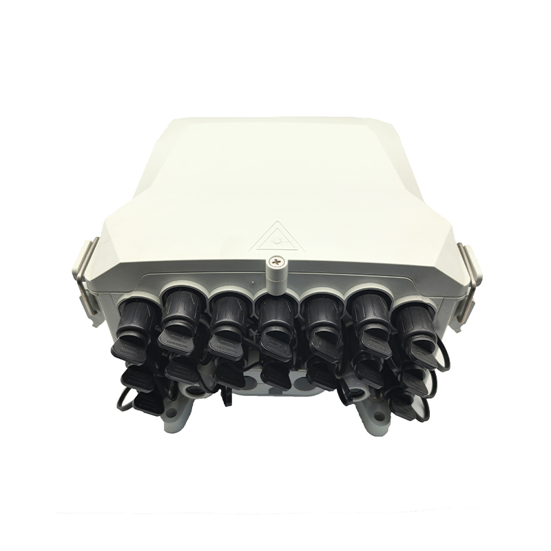
Cable Structure Materials: Strength Members, Buffer Tubes, and Jackets
Beyond the fiber itself, the outer cable structure comprises several additional material layers that protect the delicate glass fiber from mechanical stress, moisture, rodents, crushing, and UV degradation during installation and over the cable's design life of 20–25 years. Each structural component is made from materials chosen for specific protective properties.
Strength Members: Aramid Fiber, Fiberglass, and Steel
Strength members carry the tensile load applied to the cable during installation and in-service temperature cycling, protecting the optical fiber from stretching (which increases attenuation and can cause breakage). The three main strength member materials used in fiber optic cable construction are:
- Aramid Fiber Yarn (Kevlar-type): The most widely used strength member in indoor and patch cord cables. Aramid fiber has a tensile strength of approximately 3,600 MPa and a Young's modulus of 70–125 GPa — roughly five times stronger than steel at the same weight. Standard patch cords contain 150–300 denier aramid yarn; distribution cables use heavier 1,420–2,840 denier rovings. Aramid is non-conductive (important for electrical isolation) and has low thermal expansion, keeping the fiber strain-neutral across temperature changes.
- Fiberglass Reinforced Plastic (FRP) Rod: A central FRP rod (typically 0.5–3 mm diameter) is used as the central strength member in loose-tube outdoor cables. FRP offers high compressive strength (unlike aramid, which buckles under compression), making it suitable for cables that must resist crushing forces in buried or duct installations. FRP rods have a tensile strength of 1,000–1,500 MPa and, like aramid, are non-conductive.
- Steel Wire and Steel Tape: Steel strength members are used in self-supporting aerial cables (ADSS and figure-8 designs), armored cables for direct burial, and submarine cables. Steel provides the highest tensile load capacity — a 6 mm steel wire strand can sustain tensile loads above 20 kN — but adds weight and requires electrical bonding and grounding in installations near power lines. Galvanized steel or stainless steel is used depending on corrosion exposure requirements.
Buffer Tubes: PBT, PVDF, and Polypropylene
Buffer tubes are hollow cylindrical structures that contain and protect individual optical fibers or fiber ribbons within the cable. They serve two functions: protecting the fibers from lateral pressure and providing a controlled thermal expansion buffer that prevents fibers from being placed in tension during cold temperature shrinkage of the cable. The most common buffer tube materials are:
- Polybutylene Terephthalate (PBT): The industry-standard material for loose-tube buffer tubes in outdoor cables. PBT offers excellent dimensional stability across temperature (-40 to +70°C), low moisture absorption (less than 0.1%), good chemical resistance, and a wall thickness of 0.3–0.6 mm that provides meaningful crush resistance. PBT tubes are typically filled with a water-blocking gel (thixotropic hydrocarbon gel) or dry water-blocking tape to prevent moisture ingress.
- PVDF (Polyvinylidene Fluoride): Used in tight-buffer construction for indoor cables and harsh chemical environments. PVDF provides superior resistance to UV radiation, flame, and a wide range of chemicals, making it suitable for industrial premises cabling and plenum-rated indoor installations. PVDF tight-buffer coatings are applied at 900 micrometers outer diameter directly over the 250-micrometer coated fiber.
- Polypropylene (PP): A lower-cost alternative to PBT for some short-distance distribution cable applications, particularly in indoor-outdoor hybrid designs. PP has slightly lower dimensional stability than PBT at elevated temperatures but offers excellent chemical resistance and good processing characteristics for high-speed cable manufacturing.
Water Blocking Materials: Gel, Tape, and Powder
Water ingress is one of the primary causes of fiber optic cable failure in buried and direct-burial installations. Three approaches to water blocking are used, each with distinct material systems:
- Hydrocarbon Filling Gel: Traditional water blocking in loose-tube cables uses a thixotropic petroleum-based gel that fills the buffer tube and interstices between tubes. The gel remains fluid enough to allow fiber movement within the tube but viscous enough to prevent water migration. Gel-filled cables require special gel-cleaning procedures during splicing and termination.
- Superabsorbent Polymer (SAP) Tape and Yarn: Dry water-blocked cables use SAP-coated tapes or yarns that swell rapidly on contact with water (absorbing up to 400 times their own weight), blocking water migration without the mess of petroleum gel. SAP-based water blocking now dominates new cable designs due to easier handling and environmental preferences over petroleum gel.
- SAP Powder in Buffer Tubes: Some cable designs incorporate SAP powder dusted inside buffer tubes as the primary water-blocking mechanism, achieving the light weight of dry-block construction with simpler manufacturing than SAP tape wrapping.
Armor Layers: Corrugated Steel, Aluminum, and Polyethylene
Armored fiber optic cables include metallic or dielectric armor layers between the core and outer jacket to resist crushing, rodent attack, and mechanical impact. The three main armor types are:
- Corrugated Steel Tape (CST) Armor: A longitudinally applied corrugated steel tape (typically 0.15–0.25 mm thick) bonded to an inner polyethylene jacket. CST armor provides excellent crush resistance (typically rated at 3,000–4,000 N/100 mm) and rodent resistance for direct-buried cables in areas with known rodent activity.
- Corrugated Aluminum Tape: Used in submarine and some direct-burial cables where the lower weight of aluminum versus steel is advantageous. Aluminum is also more corrosion-resistant in salt-water environments.
- Interlocked Armor: Galvanized steel wires wound helically around the cable provide flexible armor for indoor-outdoor riser cables that require both rodent resistance and installation flexibility around bends.
Outer Jacket Materials: Polyethylene, PVC, LSZH, and PVDF
The outer jacket is the first line of defense against physical damage, UV radiation, moisture, chemicals, and temperature extremes. Jacket material selection has significant implications for fire safety, environmental compliance, installation ease, and long-term durability.
| Jacket Material | UV Resistance | Flame Rating | Temperature Range | Toxic Smoke | Typical Application |
| HDPE (Black) | Excellent | Not flame-retardant | -60 to +70 deg C | Low | Outdoor, direct-burial, aerial |
| PVC | Moderate | Flame-retardant (CM/CMR) | -20 to +60 deg C | High (HCl gas) | Indoor, general purpose, patch cords |
| LSZH | Good | Flame-retardant (IEC 60332) | -20 to +70 deg C | Very Low | Data centers, transit, public buildings |
| PVDF (Plenum) | Excellent | Plenum-rated (CMP/OFCP) | -40 to +85 deg C | Low | Plenum air-handling spaces, hospitals |
| TPU | Good | Flame-retardant grades available | -40 to +80 deg C | Moderate | Industrial, robotics, drag chain cables |
| Polyurethane (PUR) | Good | Not inherently flame-retardant | -55 to +80 deg C | Moderate | Military, aerospace, harsh flex cycles |
Table 2: Comparison of outer jacket materials used in fiber optic cables across UV resistance, flame rating, temperature range, smoke toxicity, and typical deployment environment.
How Fiber Optic Glass Is Made: The Preform and Drawing Process
Understanding what fiber optic cables are made of is incomplete without understanding how the ultra-pure silica glass is produced — a process that is as remarkable as the fiber's optical performance.
Preform Fabrication
The optical fiber starts as a glass preform — a solid rod of ultra-pure silica approximately 1 meter long and 80–160 mm in diameter — that contains the core-cladding refractive index structure at large scale. The most widely used preform fabrication process is Modified Chemical Vapor Deposition (MCVD), in which silicon tetrachloride (SiCl4) and germanium tetrachloride (GeCl4) vapors are oxidized inside a rotating silica tube at 1,500–1,900°C, depositing successive layers of doped and undoped glass soot. Outside Vapor Deposition (OVD) and Vapor Axial Deposition (VAD) are alternative processes used by different manufacturers to achieve higher deposition rates and larger preform sizes.
Fiber Drawing
The preform is fed vertically into a drawing furnace where its tip is heated to approximately 2,000°C — just below silica's softening point — and a thin fiber is pulled downward at speeds of 10–25 meters per second. As the fiber exits the furnace and cools, it passes through UV-curing chambers that apply and cure the dual-layer acrylate coating, then onto a take-up drum. The entire process from preform tip to coated fiber takes place in a precisely controlled atmosphere to prevent surface contamination that would reduce fiber strength. Tensile strength of the drawn fiber is continuously proof-tested on-line at stresses of 1% strain (approximately 0.7 GPa) to guarantee minimum break strength in the finished cable.
Frequently Asked Questions About Fiber Optic Cable Materials
Q1: Is fiber optic cable made of glass or plastic?
Most telecommunications and data networking fiber optic cables are made with a silica glass core and cladding. Plastic optical fiber (POF) exists and uses a PMMA or perfluorinated polymer core, but accounts for a small fraction of installed fiber globally — primarily in automotive, decorative, and short-distance sensor applications. When people refer to "fiber optic cable" in a network or internet infrastructure context, they almost always mean glass-core silica fiber.
Q2: Why is silica glass used for fiber optic cables instead of other materials?
Silica glass is used because it achieves the lowest optical attenuation of any material at the wavelengths used in telecommunications (1310 nm and 1550 nm). Its attenuation of 0.18–0.20 dB/km allows signals to travel 40 km or more without amplification. No other solid transparent material comes close to this performance at these wavelengths. Silica also has excellent chemical stability, is not hygroscopic, can be drawn into extremely uniform fibers, and its optical properties are well understood after decades of research and commercial production.
Q3: What is inside the protective jacket of a fiber optic cable?
Inside the outer jacket of a typical loose-tube outdoor fiber optic cable, you will find: a central FRP or steel strength rod, multiple color-coded PBT buffer tubes (each containing 6–12 color-coded optical fibers in water-blocking gel or surrounded by SAP tape), aramid fiber yarn or additional steel wire strength members wrapped around the tube bundle, and in armored versions, a corrugated steel tape between the tube bundle and the outer jacket. Indoor tight-buffer cables have a simpler construction: each fiber has a 900-micrometer PVDF or nylon tight-buffer layer directly over the 250-micrometer coating, with aramid yarn strength members under the outer jacket.
Q4: How pure is the glass in a fiber optic cable?
The silica glass in a telecommunications fiber optic cable is among the purest materials manufactured commercially. Total metallic impurity content is below 1 part per billion (ppb) for transition metals such as iron, copper, and chromium — elements that absorb light at telecommunications wavelengths and would dramatically increase attenuation. This purity level, exceeding 99.9999% SiO2, is achieved through the chemical vapor deposition process, which builds the glass from ultra-pure gaseous precursors (SiCl4 with purity greater than 99.9999%) rather than from natural quartz that contains unavoidable trace mineral contamination.
Q5: Can fiber optic cables withstand outdoor weather conditions?
Yes, outdoor-rated fiber optic cables are specifically engineered to survive 20–25 years of exposure to UV radiation, temperature cycling, moisture, wind loading, and in some cases rodents or crushing. Black HDPE jacketed cables contain carbon black (2–3% by weight) that absorbs UV radiation and prevents polymer chain degradation that would cause brittleness and cracking over time. The gel-filled or dry-blocked loose-tube construction prevents moisture from reaching the glass fiber, since water ingress combined with mechanical stress accelerates stress corrosion fatigue in silica. Cables installed aerially must also withstand ice loading and wind-induced vibration fatigue — requirements addressed by appropriate cable sag design and strength member sizing.
Q6: What is the difference between LSZH and PVC jacket materials?
PVC (polyvinyl chloride) jackets are flame-retardant and low-cost, but release hydrogen chloride (HCl) gas and dense black smoke when burned — toxic and corrosive in confined spaces such as data centers, transit tunnels, or occupied buildings. LSZH (Low Smoke Zero Halogen) jackets are formulated from halogen-free polymers (typically polyolefin compounds with mineral-based flame retardants such as aluminum trihydrate) that, when exposed to fire, produce minimal smoke and no halogenic acid gases. European cable standards (EN 50575) and many national building codes now require LSZH cables in public buildings, transportation infrastructure, and densely populated data center environments. LSZH cables typically cost 15–30% more than equivalent PVC-jacketed cables.
Q7: Does the fiber optic cable jacket material affect signal transmission performance?
The jacket material itself has no direct effect on light transmission through the fiber, since light travels only within the glass core and cladding. However, jacket material indirectly affects optical performance in two ways: first, stiffer jacket materials impose greater lateral forces on the fiber bundle, potentially causing microbend-induced attenuation increases if buffer tube or fiber coating designs are not optimized; second, jacket materials with poor dimensional stability at temperature extremes (particularly materials that shrink significantly at low temperatures) can place the fiber in compressive or tensile stress if the cable design does not provide adequate strain relief. Well-designed cables using standard jacket materials maintain their specified attenuation performance across the full rated operating temperature range.
Conclusion: Why Material Selection Defines Fiber Optic Cable Performance
The answer to what materials fiber optic cables are made of reveals a sophisticated, layer-by-layer engineering system in which every material is chosen with precision: ultra-pure germanium-doped silica for a core that guides light with minimal loss, undoped or fluorine-doped silica cladding that creates the total internal reflection boundary, dual-layer UV-cured acrylate coatings that protect the glass from microbend and moisture, and an outer cable structure of aramid or FRP strength members, PBT buffer tubes, water-blocking SAP materials, optional steel armor, and a jacket compound matched to the fire safety, UV resistance, temperature range, and environmental requirements of the deployment.
Each material layer plays an irreplaceable role. The failure of any single component — a diaphragm crack in the coating, water ingress through a compromised jacket, or UV degradation of an unprotected outdoor sheath — can compromise the performance or service life of an entire cable link. For network designers, installers, and procurement engineers, understanding the materials that make up fiber optic cables is the foundation for making correct specification decisions across the full range of telecom, data center, industrial, and specialty applications.