Industry News
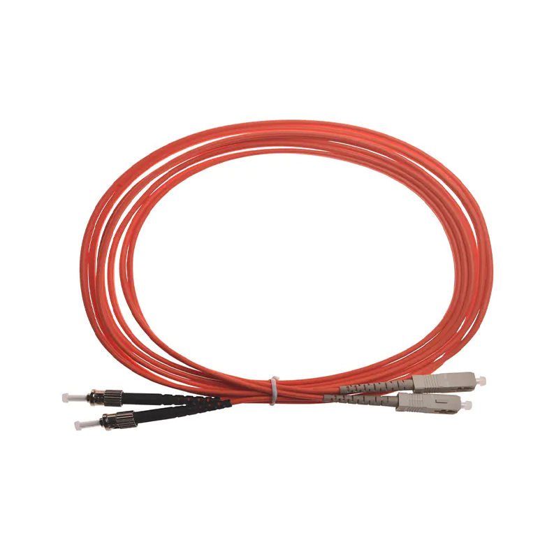
How to Test Fiber Optic Patch Cords?
2026-02-13
Fiber optic patch cords are essential connection components in fiber optic communication systems, and their performance directly affects network transmission quality and stability. So, how do you test fiber optic patch cords to ensure their performance meets standards?
Content
The Importance of Fiber Optic Patch Cord Testing
Fiber optic patch cords play a crucial role in signal transmission in data centers, communication equipment rooms, and enterprise networks. If a fiber optic patch cord has problems such as excessive attenuation, interface contamination, or excessive bending, it will lead to unstable network signals or even network outages. Industry data shows that faulty fiber optic patch cords are one of the main causes of fiber optic link failures, accounting for over 40%. Therefore, regularly testing fiber optic patch cords can help detect problems in a timely manner and ensure stable network operation.
Testing Fiber Optic Patch Cords Using an Optical Power Meter and Light Source
An optical power meter and light source are the most commonly used tools for testing fiber optic patch cords. The specific steps are as follows:
Step 1: Connect the Light Source and Optical Power Meter
Connect the light source port to one end of the fiber optic patch cord, and connect the optical power meter to the other end.
Step Two: Measure Fiber Attenuation
Under normal circumstances, the attenuation of a single-mode fiber optic patch cord should be within 0.2~0.5 dB/km, and that of a multimode fiber should be within 0.5~1 dB/km.
Step Three: Analyze Results
If the measured attenuation value is too high, check if the patch cord interface is dirty or if the patch cord itself is bent.
This method is suitable for rapid on-site testing and can intuitively determine whether the overall performance of the fiber optic patch cord meets the requirements.
Using an OTDR to Detect Detailed Location Issues in Fiber Optic Patch Cords
An OTDR (Optical Time Domain Reflectometer) can detect the end-face quality, breaks, bends, and connector losses of fiber optic patch cords. Compared to an optical power meter, an OTDR provides more precise fault location capabilities:
Locating Breaks
Through reflected signals, an OTDR can accurately display loss points in the fiber optic patch cord, with an error generally less than 1 meter.
Detecting Bending
When an abnormal attenuation peak appears in the OTDR curve, it indicates that the fiber has a bending or stretching problem.
Recording Loss Data
Test reports can be generated, facilitating long-term management by the maintenance team.
For example, during a data center cabling operation, an OTDR test revealed that a fiber optic patch cord interface had a loss as high as 1.2 dB. Timely replacement restored normal link operation and prevented potential network outages.
Fiber Optic Patch Cord Testing Precautions
During testing, the following points should be noted:
- Keep the interface clean: Fiber optic interface contamination is a major cause of abnormal test data. Dedicated fiber optic cleaning tools should be used.
- Avoid bending: During testing and installation, ensure the patch cord's bending radius is greater than the minimum bending radius. Typically, this is ≥30 mm for single-mode fiber and ≥20 mm for multimode fiber.
- Average value from multiple tests: To ensure data reliability, it is recommended to test the same fiber optic patch cord multiple times and use the average value for evaluation.
Testing fiber optic patch cords is a crucial step in ensuring the stable operation of fiber optic communication systems. Using tools such as optical power meters, light sources, and OTDRs, the performance of fiber optic patch cords can be quickly assessed, potential problems identified, and resolved promptly. Regular testing of fiber optic patch cords not only improves network reliability but also reduces maintenance costs.

get in Touch

No.255 Lianfei Road, KandunIndustrial Park, Cixi City, ZhejiangProvince, China
Product Center
contact details
-
Email: [email protected]
-
Tel: +86 18367407397
Mobile
Copyright ? Ningbo Goshining Communication Technology Co., Ltd. Fiber Optic Solutions Manufacturer Fiber Optic Products Factory
