Industry News
What is a fiber optic PLC splitter?
2025-07-23
A fiber optic PLC splitter is a passive optical device based on planar optical waveguide technology, which is used to evenly distribute input optical signals to multiple output ports, or to merge multiple optical signals into one output port. It is widely used in optical fiber communication systems, especially in passive optical network (PON) systems such as GPON, EPON, and XGS-PON.
The working principle of the fiber optic PLC splitter is based on photolithography technology, which manufactures waveguides on a silica glass substrate and realizes the conversion of optical signals through a precise optical coupling process. Its core components include an input fiber array, a planar lightwave chip, and an output fiber array. All three parts must be aligned very precisely to ensure the best transmission characteristics, including low insertion loss, low reflection loss, consistency, and high transmission parameter uniformity.
A fiber optic PLC splitter is a passive optical device based on planar optical waveguide (PLC) technology, which is widely used in optical fiber communication systems. Its technical features are mainly reflected in the following aspects:
Wide operating wavelength range: The operating wavelength range of fiber optic PLC splitters is usually between 1260nm and 1650nm, which covers the needs of most fiber optic communication applications, including FTTH (fiber to the home), PON (passive optical network) and other systems. This wide wavelength range enables PLC splitters to adapt to different types of fiber optic transmission needs, improving their applicability in a variety of application scenarios.
High reliability: PLC splitters are manufactured using semiconductor processes and have high stability and reliability. This means that they can maintain stable performance for a long time and are not easily affected by environmental changes. For example, their operating temperature range is usually -40°C to 85°C, allowing them to work normally under various climatic conditions. In addition, the structural design of PLC splitters also gives them high mechanical strength and durability, and can withstand certain physical shocks and vibrations.
Compact design: The fiber optic PLC splitter is small in size and easy to integrate into various network devices. This compact design not only saves space, but also simplifies the installation and maintenance process. For example, some PLC splitters are only 40×4×4mm to 60×12×4mm in size, which is very suitable for use in space-constrained environments. This design feature makes PLC splitters widely used in FTTH systems, CATV links, and optical signal distribution.
Low insertion loss: PLC splitters maintain consistent low insertion loss in all channels, which is essential to ensure the efficiency of optical signal transmission. Insertion loss refers to the degree of loss of optical signals when passing through the splitter. Low insertion loss means that more optical signals can be effectively distributed to each output port. For example, the insertion loss of some PLC splitters can be as low as 7.0dB (1N splitter) or 7.6dB (2N splitter), which makes them perform well in applications with high bandwidth requirements.
Good inter-channel uniformity: An important feature of PLC splitters is their good inter-channel uniformity, that is, the optical power distribution of each channel is very uniform. This uniformity ensures that the optical signal strength of all output ports is almost the same, thereby avoiding the problem of affecting overall performance due to excessive power in some channels. For example, the maximum channel uniformity of some PLC splitters can reach 0.8dB (1N splitter) or 1.0dB (2N splitter), which provides high flexibility and reliability in practical applications.
What fields can fiber optic PLC splitters be applied to?
Fiber optic PLC splitters are passive optical devices based on planar light waveguide (PLC) technology. They are widely used in modern communication systems. Their main function is to evenly distribute input optical signals to multiple output ports, or to combine multiple input signals into one output signal. This technology plays an important role in many key areas. The following are its specific applications in different fields:
1. FTTH (Fiber to the Home):
In FTTH networks, PLC splitters are used to connect the central office (OLT) and terminal devices (such as home routers, set-top boxes, etc.) to realize the branching and distribution of optical signals. By distributing the signal of one optical fiber to multiple user ends, PLC splitters significantly reduce the amount of optical fiber used, reduce deployment costs, and improve the flexibility and scalability of the network.
2. PON network:
In passive optical network (PON) systems such as GPON, EPON and XGS-PON, PLC splitter is a key component connecting optical line terminal (OLT) and optical network unit (ONU). It allows a single optical fiber to serve multiple users without using any active equipment, thus reducing the complexity and maintenance cost of the system. In addition, PLC splitter also supports high split ratio (such as 1:64 or 1:128) in PON network to meet the needs of large-scale user access.
3. Cable TV (CATV) system:
In cable TV system, PLC splitter is used to evenly distribute the input TV signal to multiple home users. By distributing the signal of a single optical fiber to multiple output ports, PLC splitter can efficiently transmit high-quality video and audio signals to multiple users, ensuring the stability and consistency of the signal.
4. Data center:
In the data center, PLC splitter is used to split the optical signal between different servers and network equipment to ensure efficient data transmission. By combining multiple input signals into one output signal, or vice versa, PLC splitters can optimize the distribution of optical signals in data centers, improve bandwidth utilization and reduce the need for separate optical fibers.
5. Industrial Automation:
In the field of industrial automation, PLC splitters are used for long-distance signal transmission to achieve efficient and synchronous operation. By distributing optical signals to multiple sensors or actuators, PLC splitters can ensure real-time communication and control between industrial equipment, improve production efficiency and safety.
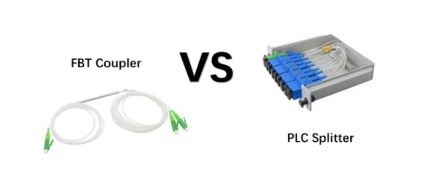
What is the difference between PLC and FBT splitters?
PLC (planar optical waveguide) splitter and FBT (fused taper) splitter are two common optical fiber splitters, which have significant differences in technical principles, performance, application scenarios, etc. The following is a detailed comparison of them:
1. Technical Principle
PLC splitter: Based on planar optical waveguide technology, waveguides are created using photolithography methods on a quartz substrate to achieve uniform distribution of optical signals. Its structure includes a substrate, a waveguide and a cover plate, and the waveguide plays a key role in the beam splitting process.
FBT splitter: Using traditional technology, multiple optical fibers are fused by heating, and then stretched with a tapered machine to align the optical fibers. The fused optical fibers are protected by epoxy resin and silica glass tubes, and then sealed with stainless steel tubes and silicone.
2. Working wavelength range
PLC splitter: Supports a wide wavelength range of 1260nm to 1650nm, suitable for a variety of application environments.
FBT splitter: Limited to three specific wavelengths of 850nm, 1310nm and 1550nm, limited flexibility.
3. Branching ratio and uniformity
PLC splitter: Provides fixed standard branching ratios such as 1:2, 1:4, 1:8, 1:16, 1:32 and 1:64, and all branches have the same branching ratio, and the signal distribution is uniform.
FBT splitter: Provides variable and customized branching ratios, but cannot guarantee an exact equal division ratio, and the signal distribution is uneven.
4. Size and packaging
PLC splitter: compact structure, small size, suitable for space-constrained applications, such as inside optical network terminals.
FBT splitter: larger size, especially at high split ratios, the package module is larger.
5. Failure rate and reliability
PLC splitter: low failure rate, especially better performance at high split ratios, wider operating temperature range (-40°C to 85°C).
FBT splitter: high failure rate, especially at split ratios exceeding 1:8, prone to failure due to extreme temperatures or improper operation.
6. Cost
PLC splitter: complex production process, high cost, but may be more expensive than FBT splitter at smaller split ratios.
FBT splitter: easy to obtain and inexpensive materials, low production cost.
7. Application scenarios
PLC splitter: suitable for application scenarios that require larger split configurations, such as FTTx networks, PON systems, etc.
FBT splitter: suitable for network configurations that require less than 4 splitters, especially 1x2 and 1x4 types have good cost-effectiveness.
PLC splitters are superior to FBT splitters in terms of operating wavelength range, split ratio uniformity, failure rate and reliability, but the cost is higher. FBT splitters have more advantages in cost and specific wavelength applications, but are limited by split ratio and signal uniformity. The choice of which splitter depends on the specific application requirements and the trade-off between cost, performance and reliability.
How does the PLC splitter work in the FTTH network? How to use the PLC splitter in the FTTH network?
1. Working principle of PLC splitter
PLC splitter is a passive optical device based on planar optical waveguide technology, which is widely used in modern optical fiber communication systems. Its core principle is to use photolithography technology to create multiple parallel waveguide structures on a high-purity quartz glass substrate. These waveguides achieve uniform distribution of optical signals during beam propagation.
1.1 Structural composition
Input fiber array: introduces the optical signal from OLT (optical line terminal) into the PLC chip.
PLC chip: consists of multiple layers of silica glass, and forms a precise waveguide path through photolithography to realize the splitting of optical signals.
Output fiber array: distributes the split optical signal to multiple ONTs (optical network terminals) or user devices.
1.2 Working process
The optical signal enters the PLC chip from the input port;
Inside the chip, the optical signal is evenly distributed to multiple output ports through the waveguide structure;
The output port transmits the optical signal to each user terminal (such as home router, set-top box, etc.) through the fiber array.
1.3 Key performance indicators
Insertion loss: The loss of the optical signal when passing through the splitter is usually between 7dB and 12dB, depending on the splitting ratio and the number of channels.
Channel uniformity: The difference in optical power between each output channel is usually required to be less than 1dB.
Working wavelength range: usually 1260nm~1650nm, suitable for a variety of transmission needs.
Isolation: The degree of isolation between different channels is usually required to be greater than 40dB to prevent signal crosstalk.
2. How PLC splitters are used in FTTH networks
2.1 Overview of FTTH network architecture
FTTH (Fiber to the Home) is an access method that directly deploys optical fiber to users' homes or buildings. It is one of the most mainstream broadband access technologies. Its typical architecture includes:
OLT (Optical Line Terminal): Located in the central office, responsible for communicating with multiple users.
ONU (Optical Network Unit): Located at the user end, responsible for converting optical signals into electrical signals.
Splitter: Located between OLT and ONU, used to distribute the signal of one optical fiber to multiple users.
2.2 The role of PLC splitter in FTTH
In the FTTH network, the main function of the PLC splitter is to evenly distribute the optical signal from the OLT to multiple users, thereby realizing the efficient transmission mode of "one source for multiple uses". This technology is called Passive Optical Network (PON), and its core advantages are:
Save fiber resources: one fiber can serve multiple users, reducing fiber laying costs.
Simplify network structure: no active equipment is required, reducing maintenance complexity.
Support high bandwidth: suitable for high-bandwidth PON systems such as GPON, EPON, and XGS-PON.
2.3 Typical application scenarios of PLC splitters
In the first-level splitting, the PLC splitter is usually installed in the optical cable splitter box, directly connecting the OLT and multiple user terminals. This configuration is suitable for areas with high user density and close distance.
Typical configuration: 1×N (N=4~64) splitter, that is, one input fiber is connected to N output fibers.
Advantages: Save fiber resources and flexible deployment.
Disadvantages: High performance requirements for the splitter, especially when the split ratio is high (such as 1×64).
In the second-level splitting, the PLC splitter is cascaded to form a two-level splitting structure. This configuration is suitable for scenarios where users are widely distributed and far away.
Typical configuration: primary splitter (1×4) + secondary splitter (1×8), supporting a total of 32 users.
Advantages: wider coverage, suitable for rural or remote areas.
Disadvantages: increased deployment complexity and slightly higher cost.
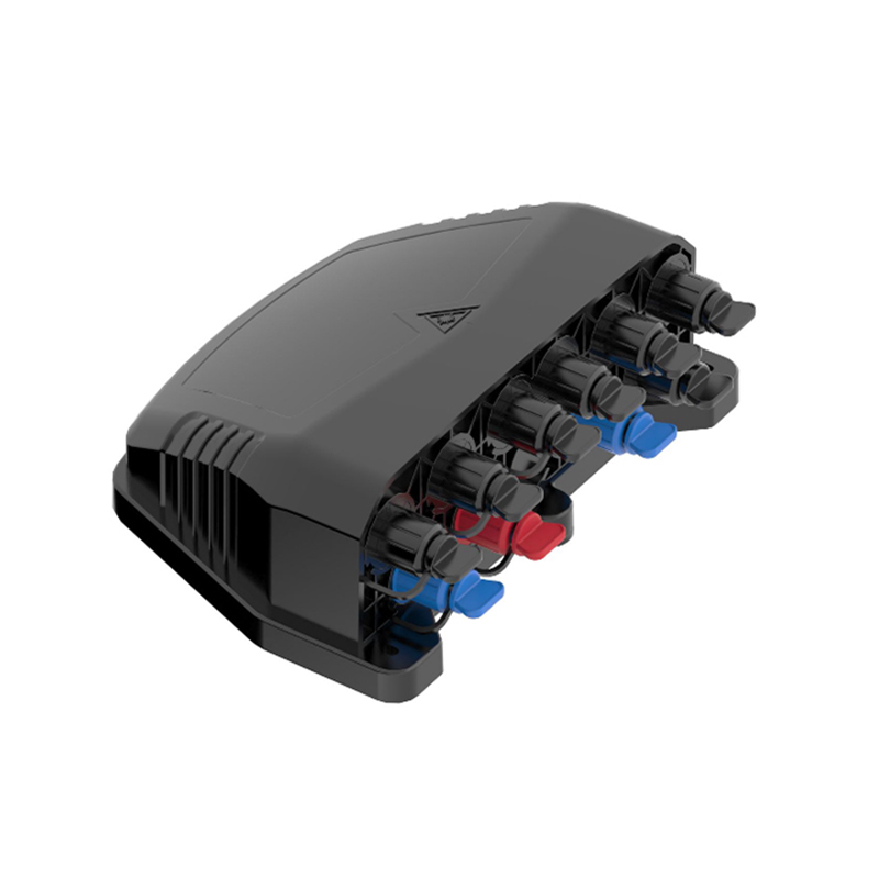
According to actual deployment needs, PLC splitters have a variety of packaging forms, suitable for different scenarios:
| Packaging type | Applicable scenarios |
| Bare fiber (mini module) | Compact devices, such as small access points |
| ABS box type | Small access devices, easy to install |
| LGX box type | Medium-sized access devices, suitable for buildings |
| Rack type | Large network deployments, such as data centers |
3. Advantages of PLC splitters in FTTH
3.1 High reliability and stability
PLC splitters are manufactured using semiconductor processes, with high consistency and stability, suitable for various environmental conditions.
The operating temperature range is usually -40°C to 85°C, with strong adaptability.
3.2 Low insertion loss and high uniformity
Low insertion loss ensures high efficiency of optical signal transmission.
Even power distribution between channels to avoid performance degradation caused by signal imbalance.
3.3 Wide operating wavelength range
Supports a wide wavelength range of 1260nm~1650nm, suitable for a variety of transmission needs, such as CATV, data transmission, etc.
3.4 High cost-effectiveness
Compared with FBT (fused taper) splitters, PLC splitters have more cost advantages at high split ratios.
Suitable for large-scale deployment, reducing the overall network construction cost.
3.5 Easy to install and maintain
Passive devices, no external power supply required, simplifying the installation and maintenance process.
Various packaging forms, easy to integrate into different devices.
4. Comparison between PLC splitters and FBT splitters
| Features | PLC splitter | FBT splitter |
| Technical principle | Photolithography, waveguide structure | Fused taper, physical alignment |
| Branch ratio uniformity | High, small difference between channels | Low, large difference between channels |
| Insertion loss | Low, good consistency | High, easy to fluctuate |
| Operating wavelength | Wide (1260nm~1650nm) | Limit (850nm, 1310nm, 1550nm) |
| Size | Small, suitable for compact equipment | Large, suitable for low split ratio |
| Cost | High, but superior performance | Low, suitable for small-scale deployment |
| Application scenario | FTTH, PON, data center | Low split ratio, low-cost scenario |
With the continuous expansion of FTTH deployment, the application of PLC splitters will become more extensive, especially in scenarios that support high bandwidth requirements such as 10G/25G PON, its advantages will be more obvious. In the future, with the further optimization of manufacturing processes and the reduction of costs, PLC splitters are expected to play an important role in more fields and promote the continuous development of optical communication technology.
What are the common packaging forms of fiber optic PLC splitters?
Common packaging forms of fiber optic PLC splitters include bare fiber (mini module), ABS box, LGX box and rack, and each packaging form has its specific application scenarios and advantages.
Bare fiber (mini module): This packaging form has no connector, and the input and output are designed as bare fiber, usually using ribbon fiber output. Bare fiber splitters are suitable for occasions that are not often disassembled, such as cable connector boxes, fiber optic distribution boards, etc.
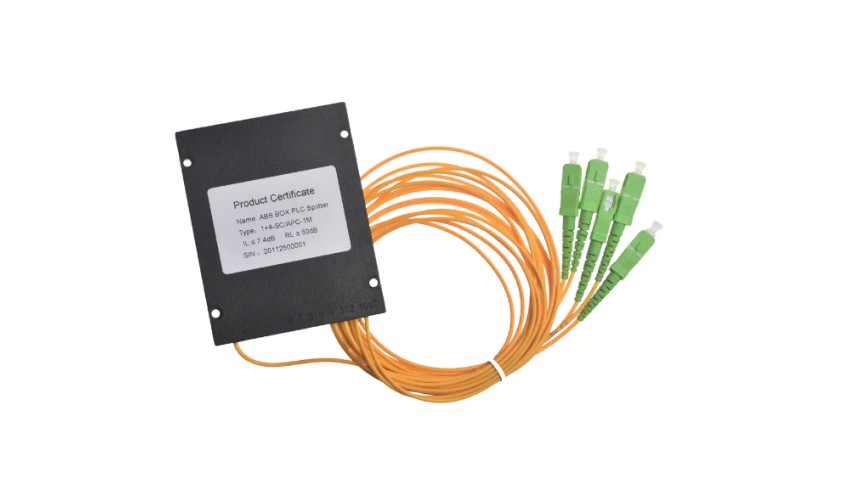
ABS box: ABS box PLC splitters use plastic ABS shells to provide good optical components and cable protection. This packaging form is compact and flexible to install, suitable for installation in various wiring cabinets or chassis. The input end fiber and the output end fiber are on a layer of splitter waveguide made of quartz substrate. The structure is compact and small, which can provide easier and more flexible wiring. It can be directly installed in various existing junction boxes without leaving a large installation space.
LGX Cassette: The LGX Cassette PLC splitter has a sturdy metal box and can be used independently or installed in a standard fiber distribution frame or fiber chassis. This packaged splitter is pre-terminated with a fiber adapter, which can quickly achieve reliable fiber connection and is suitable for plug-and-play network integration. It does not require file fusion or technician intervention, reducing the risk during installation.
Rack-mounted: The rack-mounted PLC splitter is designed for standard 19-inch cabinet installation and can meet the requirements of high wiring density in data centers or server rooms.
This packaged splitter is generally packaged in a metal box, which is easy to install in fiber optic projects and provides good protection for PLC splitter devices. There are various adapter installation interfaces, such as SC, LC, FC or ST connectors, which are widely used in FTTX projects, cable TV systems and data communication centers.
| Packaging type | Features | Applicable scenarios | Advantages |
| Bare fiber (mini module) | No connector, bare fiber input and output, usually ribbon fiber output | Occasions where disassembly is not frequent, such as cable connector boxes, fiber distribution boards, etc. | Small size, compact structure, suitable for installation environments with limited space |
| ABS box type | Plastic ABS shell, compact structure, small size | Installed in wiring cabinets or chassis, suitable for small devices such as junction boxes | Flexible installation, easy wiring, suitable for access networks such as FTTH and PON |
| LGX box type | Sturdy metal box package, pre-terminated with fiber adapter | In standard fiber distribution frames or chassis, suitable for plug-and-play scenarios | Easy installation, no need for welding, reducing maintenance costs and risks |
| Rack type | Designed for standard 19-inch cabinet, metal box package | Data centers, server rooms, high-density wiring requirements | Support high-density wiring, suitable for large-scale network deployment such as FTTX, CATV, and data centers |
What are the characteristics of ABS Cassette PLC optical splitters?
ABS box-type PLC optical splitter is an integrated waveguide optical power distribution device based on quartz substrate. It is widely used in passive optical network (PON) systems to evenly distribute optical signals from the central office (OLT) to multiple end users (ONT). Its features are as follows:
Compact structure: The ABS box-type PLC optical splitter is encapsulated in a plastic ABS shell, which is small in size and compact in structure, easy to install and maintain. This design allows it to be easily installed in various wiring cabinets or chassis without taking up a lot of space.
Good splitting uniformity: Due to the use of planar optical waveguide technology, the ABS box-type PLC optical splitter can achieve uniform distribution of optical signals, and the power difference between each channel is extremely small, usually less than 1dB, ensuring the stability and consistency of signal transmission.
Low insertion loss and low polarization-dependent loss (PDL): The ABS box-type PLC optical splitter has the characteristics of low insertion loss and low PDL, which makes the optical signal less lost during transmission and improves the overall performance of the system.
Wide operating wavelength range: The operating wavelength range of ABS box-type PLC optical splitter is usually 1260nm to 1650nm, which is suitable for a variety of transmission needs, including FTTH, PON, CATV and other systems.
High reliability and stability: ABS box-type PLC optical splitter adopts high-quality materials and advanced manufacturing technology, has good environmental adaptability and stability, and can operate normally in the operating temperature range of -40°C to 85°C.
Easy to install and maintain: The structural design of ABS box-type PLC optical splitter makes it easy to install without complicated debugging process. In addition, its modular design is also easy to maintain and replace.
Compliance with international standards: ABS box-type PLC optical splitter complies with international standards such as Telcordia GR-1209-CORE and GR-1221-CORE, ensuring its compatibility and reliability in practical applications.
Diverse splitting modes: ABS box-type PLC optical splitter provides multiple splitting modes such as 1×N and 2×N to meet the needs of different application scenarios, such as 1×2, 1×4, 1×8, 1×16, 1×32, 1×64, etc.
Environmental protection and safety: ABS box-type PLC optical splitter is made of high-quality ABS material, which complies with the European ROHS environmental protection standard, ensuring the environmental protection and safety of the product.
| Features | Description | Advantages/Description |
| Compact structure | Encapsulated in plastic ABS shell, small size and compact structure | Easy to install in various wiring cabinets or chassis, saving space, suitable for environments with limited space |
| Good spectral uniformity | Using planar light waveguide (PLC) technology to achieve uniform distribution of optical signals | The power difference between channels is extremely small (usually less than 1dB), ensuring the stability and consistency of signal transmission |
| Low insertion loss and low PDL | Low insertion loss and low polarization-dependent loss (PDL) | Improve the overall performance of the system and reduce the loss of optical signals during transmission |
| Wide operating wavelength range | Usually 1260nm to 1650nm | Suitable for a variety of transmission needs, including FTTH, PON, CATV and other systems |
| High reliability and stability | Using high-quality materials and advanced manufacturing processes | Stable operation within the operating temperature range of -40°C to 85°C, adapting to various environmental conditions |
| Easy to install and maintain | Modular design, easy installation, no complex debugging required | Easy to maintain and replace, reducing maintenance costs and time |
| Comply with international standards | Complies with Telcordia GR-1209-CORE and GR-1221-CORE standards | Ensure the compatibility and reliability of the product in actual applications |
| Diverse spectral modes | Provides multiple splitting modes such as 1×N and 2×N | Meet the needs of different application scenarios, such as 1×2, 1×4, 1×8, 1×16, 1×32, 1×64, etc. |
| Environmentally friendly and safe | Using high-quality ABS material, in line with European ROHS environmental protection standards | Ensure the environmental protection and safety of the product, in line with the requirements of modern green communications |

get in Touch

No.255 Lianfei Road, KandunIndustrial Park, Cixi City, ZhejiangProvince, China
Product Center
contact details
-
Email: [email protected]
-
Tel: +86 18367407397
Mobile
Copyright ? Ningbo Goshining Communication Technology Co., Ltd. Fiber Optic Solutions Manufacturer Fiber Optic Products Factory
