English
 Español

 Inquiry
The core is the light-guiding center of a fiber optic cable. In ordinary communications fiber it is a 9 µm glass core in single-mode cable, or a 50 µm or 62.5 µm core in multimode cable, surrounded by a 125 µm cladding. That core diameter and refractive-index profile set the fiber’s mode count, attenuation, bend sensitivity, splice loss, and the transceivers that will work at each end. A core mismatch is easy to miss on a quote and expensive to discover after installation; this guide covers the practical checks.
Content
What the Core Does and How Light Travels
The core carries light by total internal reflection, not by a hollow tube. It is usually high-purity silica, doped to raise its refractive index slightly above the cladding. Light launched inside the acceptance angle reflects at the core-cladding boundary and stays in the core. The core’s numerical aperture and diameter decide how many paths, or modes, the fiber supports. Single-mode fiber has an 8–10 µm core and a mode field diameter near 9.2 µm at 1310 nm; multimode fiber uses a wider core so several modes travel at once. The 125 µm cladding, not the core, is the mechanical alignment reference for connectors and splices. Coating and buffer dimensions—often 250 µm and 900 µm—matter when you select strippers, connectors, and closure trays. For a broader view of cable layers, see this guide to fiber optic cable construction.
Single-Mode vs Multimode Core: A Practical Comparison
Single-mode core is the default when distance and loss budget matter; multimode is the practical choice for short, high-count links. The table summarizes the usual sizes and where each fits.
| Core type | Typical core/cladding | Light path | Typical fit | Check before purchase |
|---|---|---|---|---|
| Single-mode OS1/OS2 | 9/125 µm | One mode | Access, metro, long haul | G.652.D or G.657 class; 1310/1550 nm optics |
| Multimode OM3/OM4 | 50/125 µm | Multiple modes | Data centers, campus | Modal bandwidth; 850 nm optics; reach at target speed |
| Legacy multimode OM1/OM2 | 62.5/125 µm or 50/125 µm | Multiple modes | Existing short links | Do not mix 62.5 and 50 µm without a loss budget |
| Bend-insensitive single-mode | 9/125 µm | One mode | Tight conduit, indoor risers | G.657.A1/A2; bend radius and loss limit |
Single-mode systems commonly reference ITU-T G.652.D for standard low-loss access and metro links, or G.657.A1/A2 where tighter bends are expected. Multimode systems use 50 µm cores in OM3, OM4, and OM5 grades; 62.5 µm cores remain in legacy OM1/OM2 plants. The core size alone does not guarantee performance: modal bandwidth, jacket construction, and connector quality also matter. A 50 µm to 62.5 µm splice is not a neutral connection; the core mismatch produces loss and reflection, so keep the two fiber types on separate links or use a purpose-built mode conditioner where the design allows it.
Core Size, Tolerance, and Connector Fit
Nominal core size is a specification target, not a manufacturing guarantee to the third decimal. Standards allow tolerances on core diameter, core non-circularity, and core/cladding concentricity. Those tolerances affect splice loss and connector alignment, especially in field-terminated connectors. For a 125 µm cladding fiber, the connector ferrule aligns the cladding; the core must sit close to the center. A high concentricity error can push loss up even when the cable print says 9/125 µm. Field practice matters too: strip without nicking the cladding, cleave within the connector maker’s angle limit, and use the correct 250 µm or 900 µm boot. Factory-terminated assemblies remove field polish and epoxy variables from the link.
 LC UPC to LC UPC Single-Mode Duplex Fiber Patch CordSingle-mode duplex LC/UPC patch cord for fiber signal transmission; review connector details and loss budget before comparing single-mode link options.View Product →
How Core Choice Changes Loss, Distance, and Cost
Core choice changes the loss budget more than many buyers expect. Single-mode fiber has lower attenuation over distance; multimode fiber can use lower-cost short-reach optics. A typical single-mode link may be budgeted near 0.35 dB/km at 1310 nm and 0.20 dB/km at 1550 nm, while multimode OM3/OM4 loss at 850 nm is commonly around 3.5 dB/km. Those figures are starting points, not a design guarantee; splices, connectors, and bends add loss. Distance also interacts with speed. OM4 50 µm fiber is often used for 100G links to about 150 m, while single-mode can carry the same rate for kilometers. If a quote mixes 62.5 µm and 50 µm patch cords, the core mismatch can add loss at every transition. Build the budget from the actual core size, not from the connector color.
Core Types Beyond Standard Glass
Not every core is a solid silica rod. Bend-insensitive G.657 fiber modifies the refractive-index profile so light stays guided at tighter radii, which helps in crowded cabinets and indoor risers. Hollow-core fiber guides light in an air-filled center; it can reduce latency and nonlinear effects, but it is not a drop-in replacement for every connector and splice process. Polarization-maintaining fiber adds stress members around the core to preserve polarization, and reduced-cladding fiber uses an 80 µm cladding for compact coils. These specialty cores are selected for a reason; confirm connector, splice, and test-equipment compatibility before you standardize on them.
Procurement Checklist for Core-Based Cable Selection
Specify the core and cladding together, not just “single-mode” or “multimode.” A purchase order that says only “9 µm fiber” leaves out the cladding, coating, bend class, and cable construction. Use the following checks.
- State core/cladding, for example 9/125 µm single-mode or 50/125 µm multimode.
- Name the fiber standard and bend class: G.652.D, G.657.A1/A2, OM3, OM4, or OM5.
- Give attenuation and bend-loss limits at the operating wavelengths.
- Match connectors and splices to the fiber type; do not mix 50 µm and 62.5 µm in one channel.
- Verify cable construction, water blocking, jacket material, and tensile rating for the route.
- Require test results: insertion loss, return loss, and OTDR trace where applicable.
For outdoor duct or aerial routes, cable construction has to match the core. A GYTS-style stranded loose tube cable is one option for duct and aerial outside plant, with the core count and fiber type fixed in the order.
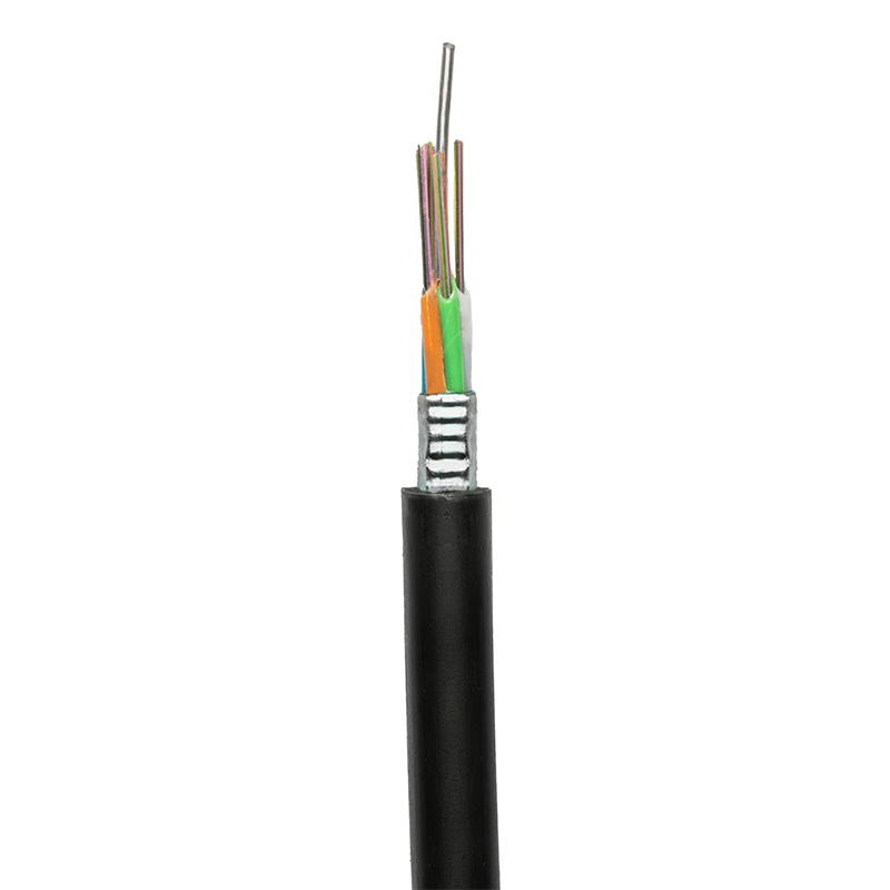 GYTS Outdoor Fiber Optic Cable for Duct and Aerial RoutesStranded loose tube cable positioned for overhead and pipeline outside plant; check fiber count and construction for duct or aerial deployment.View Product →
FAQ
Is the core always glass?
Usually yes for communications fiber; the core is doped silica, while plastic optical fiber uses a plastic core for very short links. Hollow-core fiber is a special case that guides light mainly in air. For standard single-mode and multimode cable, assume a glass core and use the datasheet to confirm the grade.
Does a larger core carry more data?
No. A larger multimode core supports more modes, but total capacity depends on transceiver technology, modal bandwidth, and distance. Single-mode’s small core carries more data over long distances because it avoids modal dispersion.
Can I splice 50 µm to 62.5 µm?
Not as a normal practice. The core mismatch creates loss and reflection, and the result may pass a quick continuity test but fail a loss budget. Keep 50 µm and 62.5 µm on separate links unless a designed mode conditioner is part of the plan.
How do I confirm core size in the field?
Read the cable print and datasheet, then verify the fiber type at the patch panel. Core size is not reliably visible at the connector end. Use an OTDR and power meter for loss, and check the connector and transceiver compatibility before pulling cable.
The fiber optic cable core is small, but it sets the optical rules for the whole link. Match core size, standard, bend class, connector, and transceiver at the design stage; then test the installed loss against the budget. That approach prevents the most common core-related surprises: a 62.5/50 µm mismatch, a bend-sensitive route, or a connector that aligns the cladding but not the light-carrying center.