Industry News
What is the working principle of a fiber optic PLC splitter?
2026-01-16
A fiber optic PLC splitter (Planar Lightwave Circuit Splitter) is a passive optical device based on planar optical waveguide technology. Its core principle is: by etching precise optical waveguide paths onto a quartz substrate, the input optical signal is evenly split into multiple output ports according to a predetermined ratio (e.g., 1:4, 1:8, 1:32, etc.) using the coupling and distribution effects of light.
This process mainly relies on the Y-shaped branch structure network inside the chip. The optical signal propagates in the waveguide, passing through a series of splitting units to achieve even energy distribution. Compared with traditional fused biconical tapered splitters, fiber optic PLC splitters have significant advantages such as high splitting accuracy, wide wavelength adaptability, strong stability, and compact size.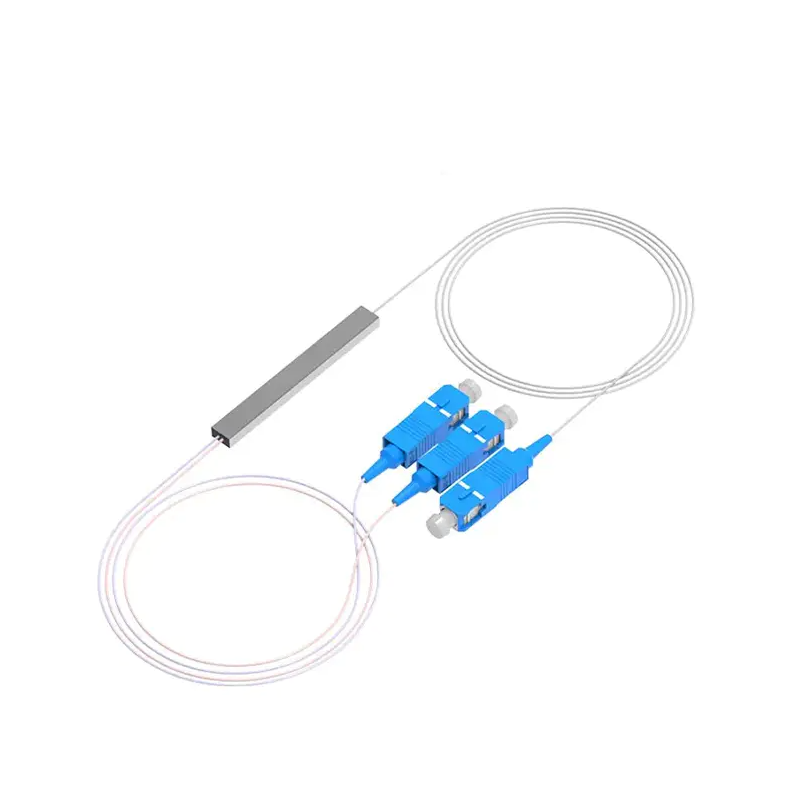
Content
I. Core Technology: How does a planar optical waveguide work?
The manufacturing process of fiber optic PLC splitters is similar to that of semiconductor chips. Its core technologies include:
- Materials and Deposition: A waveguide layer with a higher refractive index is formed on a silicon or quartz substrate using methods such as chemical vapor deposition.
- Photolithography and Etching: The designed waveguide pattern (mainly Y-shaped branch arrays) is transferred onto the waveguide layer using photolithography, and physical channels are formed through etching.
- Coupling and Packaging: The fabricated PLC chip is precisely aligned and permanently coupled to the input/output fiber optic arrays to ensure efficient transmission of optical signals.
The key to the entire process is achieving low-loss, high-consistency optical splitting, ensuring highly uniform optical power distribution at each output port.
II. Main Advantages and Application Scenarios
PLC optical splitters have become the mainstream choice for modern optical networks due to their multiple performance advantages:
- Uniform Splitting: Input optical power is evenly distributed, resulting in high splitting ratio accuracy.
- Wavelength Insensitivity: Stable performance across a wide wavelength range of 1260nm~1650nm, suitable for various communication standards.
- Compact and Stable: The chip-based design results in a small size, insensitivity to environmental temperature changes and vibration, and high reliability.
- High Channel Count: Easily implements 1×N high-channel splitting (e.g., 1×64, 1×128).
Main Application Areas:
- Fiber to the Home (FTTH) Networks: In Passive Optical Networks (PON), it serves as the core splitting device in the Optical Distribution Network (ODN), distributing central office signals to numerous end users.
- Data Center Interconnects: Used for signal distribution in optical backplanes and optical interconnect links.
- CATV Systems: Enables multi-point distribution of video optical signals.
- Testing and Sensing: Used as an optical path distribution unit in fiber optic test equipment and distributed sensor networks.
III. Future Development Trends
With the deployment of 5G, gigabit optical network upgrades, and the surge in data center traffic, the fiber optic PLC splitter market continues to grow. Future technological developments will focus on:
- Higher integration: Developing chips with more branches (e.g., 1×256) and integrating them with functions such as wavelength division multiplexing (WDM) into a single module.
- Miniaturization and low cost: Improving processes to further reduce device size and lower production costs.
- Intelligent management: Exploring integration with monitoring functions such as optical time domain reflectometers (OTDR) to achieve monitorable intelligent ODN networks.
Fiber optic PLC splitters, with their stable and efficient splitting capabilities based on planar optical waveguide technology, have become the cornerstone of building high-speed broadband optical networks. Their continuous technological evolution will strongly support the future development of all-optical networks towards higher capacity and greater intelligence.

get in Touch

No.255 Lianfei Road, KandunIndustrial Park, Cixi City, ZhejiangProvince, China
Product Center
contact details
-
Email: [email protected]
-
Tel: +86 18367407397
Mobile
Copyright ? Ningbo Goshining Communication Technology Co., Ltd. Fiber Optic Solutions Manufacturer Fiber Optic Products Factory
