English
 Español

 Inquiry
You are onsite pulling a 48-fiber loose-tube cable into a duct. At the building entry, the cable deflects around a sharp edge and you see the jacket kink. The OTDR later shows a 2.5 dB loss at that point. That loss is not a coincidence; it is the direct result of exceeding the fiber optic cable bending radius.
The fiber optic cable bending radius is the minimum radius at which the cable can be bent without causing excessive optical attenuation or permanent damage. As a working rule, keep the bend radius above 10 times the cable's outer diameter after installation and above 20 times the outer diameter while the cable is being pulled. These figures are accepted guidance from TIA and ISO structured cabling standards and are also the values most cable manufacturers use on their spec sheets.
This article explains the definition, the formula, the difference between static and dynamic limits, the factors that change the limit, and the practical installation steps that avoid bend-related failures.
Content
- 1 What Is Fiber Optic Cable Bending Radius?
- 2 Why Does the Bending Radius Matter?
- 3 Standard Bend Radius Values and How to Calculate Them
- 4 Static vs. Dynamic Bend Radius
- 5 Factors That Change the Minimum Bend Radius
- 6 Installation Practices That Prevent Bend Limit Violations
- 7 Bend Radius in Splice Closures and Distribution Boxes
- 8 Fiber Optic Cable Bending Radius FAQs
What Is Fiber Optic Cable Bending Radius?
Bending radius is the radius of the smallest circle that the cable can be bent into without exceeding the performance limits of the fiber inside. For a cable with an outer diameter of D, the minimum bending radius R is usually expressed as a multiple of D, such as 10 x D or 20 x D.
The term is sometimes confused with bend diameter. The diameter is simply two times the radius. For example, if the minimum bend radius is 60 mm, the bend diameter is 120 mm. In practice, installers work in radius because radius is what fits into corners, trays, and splice closures.
Bending becomes a problem when the radius is too small. Light propagating inside the core strikes the cladding at an angle larger than the critical angle and escapes into the coating. The result is macrobending loss, which appears as a sudden attenuation increase and, if the fiber is bent tightly enough over time, as a fatigue or fracture failure.
Why Does the Bending Radius Matter?
Exceeding the bend radius is a leading cause of hidden link loss and premature cable failures in fiber networks. Even a single tight bend can add several decibels of attenuation to a link, which is enough to reduce the optical budget and create intermittent errors in a 10G or 100G system.
The mechanical side is equally important. A sharp bend creates tensile stress on the glass fiber and compressive stress on the coating. Repeated movement at the same point can initiate microcracks, and over months or years the fiber can break. This is particularly relevant for patch cords, pigtails, and drop cables that are rerouted by technicians.
There is also a difference between the optical limit and the mechanical limit. A fiber may not break immediately when bent tightly, but the optical loss can make the link unusable. Therefore, the bending radius specification is primarily an optical performance limit, not a physical strength limit.
Standard Bend Radius Values and How to Calculate Them
The fastest way to determine a safe bend radius is to multiply the cable outer diameter by the appropriate factor. For a typical outdoor cable with an outer diameter of 12 mm, the static bend radius is 10 x 12 mm = 120 mm, and the dynamic bend radius is 20 x 12 mm = 240 mm.
| Cable condition | Minimum multiple of outer diameter | Typical example for 12 mm cable |
|---|---|---|
| During pulling (dynamic) | 20 x OD | 240 mm |
| Installed, no tension (static) | 10 x OD | 120 mm |
| Individual fiber inside splice tray or closure | Not based on cable OD | 30 to 40 mm radius |
Note that individual coated fibers inside a cable have much smaller bend limits than the cable jacket. A bare fiber can usually be bent to a radius of about 30 mm without serious loss, but the cable jacket, strength members, and buffer tubes raise the effective radius to 10 x OD or more.
For outdoor line applications, check the manufacturer's specification before you choose a cable. The cable's outer diameter and construction determine whether it will fit your conduit and slack loops.
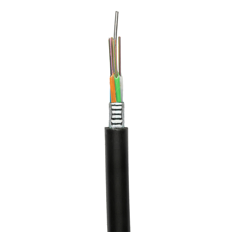 GYTS Outdoor Fiber Optic Cable for Overhead and Duct InstallationsThis armored outdoor cable offers strong mechanical strength and tensile performance, making it a dependable choice for aerial and conduit runs where bending limits and environmental durability are key concerns.View Product →
Static vs. Dynamic Bend Radius
Dynamic bending radius applies when the cable is being moved, pulled, or flexed, while static bending radius applies after the cable is fixed in its final position. The dynamic limit is always larger because tension increases stress on the fiber.
| Condition | Recommended factor | When it applies |
|---|---|---|
| Dynamic | 20 x OD | Pulling, lifting, re-routing |
| Static | 10 x OD | Final installed position |
If the cable is pulled around a bend while under tension, the combined stress from bending and pulling is higher. Some installers use 15 x OD for short, low-tension pulls, but 20 x OD is the safer default and is the figure used in classic fiber optic reference guidance.
Factors That Change the Minimum Bend Radius
The actual safe radius for your project depends on more than the "10D/20D" rule, so always check the datasheet for the specific cable you intend to use.
- Cable construction: Loose-tube outdoor cables generally have larger outer diameters and require larger radii than indoor tight-buffered cables.
- Armor layer: Corrugated steel tape armor adds stiffness and increases the minimum bend radius compared to unarmored versions.
- Fiber type: Bend-insensitive fibers such as G.657.A1 are designed for tighter radii and are useful for indoor or data center environments.
- Temperature: At low temperatures, the jacket becomes stiffer, so the effective bend limit is larger.
- Installation tension: Higher pull tension demands a larger radius, which is why the dynamic limit is 20 x OD, not 10 x OD.
When you select a cable for a route with many bends, a bend-insensitive fiber can save space, but it does not remove the cable-level limit. The outer jacket and strength members still determine the minimum radius for the whole cable assembly.
Installation Practices That Prevent Bend Limit Violations
Most bend-related failures occur at predictable locations: cable entry points, conduit corners, patch panel exits, and slack loops. The following practices help you keep the radius within limits.
- Plan the route before pulling. Walk the path and identify tight corners where a cable would bend sharply.
- Use corner pulleys or guides. A roller or curved conduit adapter holds the cable to a safe radius while it moves.
- Leave a service loop. Slack helps you place connectors and later reroute without bending the cable beyond its limit.
- Do not coil cable too tightly. Coiling at too small a diameter for storage is one of the easiest ways to create loss.
- Secure cables without crushing. Ties and clips should not compress the jacket because compression can deform the internal structure.
- Check after pulling. If the OTDR shows a loss spike near a bend point, rework the route and increase the radius before finalizing the installation.
Field-assembled connectors are popular for quick restoration and FTTH drops. When you terminate at the cable end, leave a straight section before the bend and do not kink the cable right behind the connector boot.
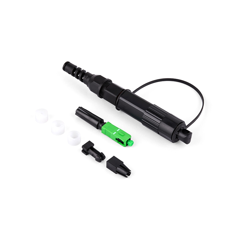
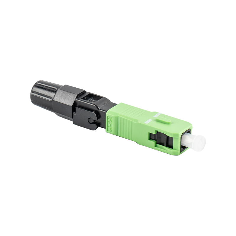
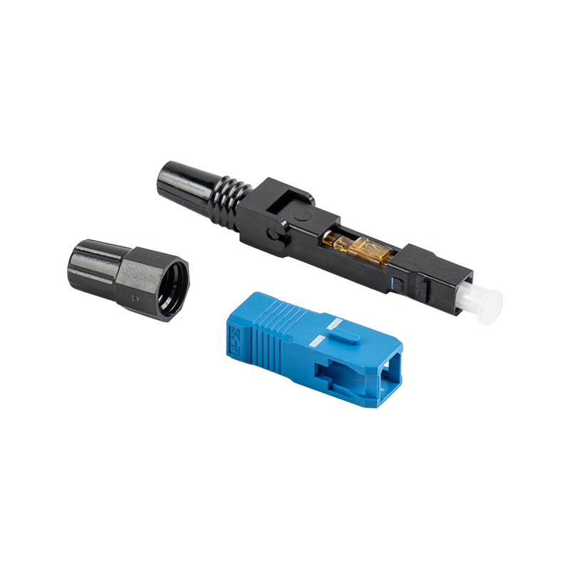 GSG-01 55mm UPC Field-Assembled Fiber Optic Fast ConnectorPre-polished and tool-free, this fast connector enables quick on-site termination for drop cables. Its compact 55mm design suits tight spaces while maintaining stable insertion loss and repeated mating cycles.View Product →
Bend Radius in Splice Closures and Distribution Boxes
Inside splice closures and fiber distribution boxes, fibers are routed individually and often wrapped around splice trays. The cable-level limit does not apply once the fibers are separated from the cable jacket; instead, the limit is defined by the fiber itself and the tray design.
Most splice trays provide bend radius limiters, usually 30 mm or more. Keep the excess fiber coiled inside the tray and do not pull it tight against the edge. In outdoor FTTH networks, pre-connected solutions reduce on-site splicing and improve bend control because factory-terminated cable assemblies are built with the correct bend radius in mind.
For outdoor access networks, a pre-connected ODN box can reduce the number of sharp bends during drop cable installation and maintenance.
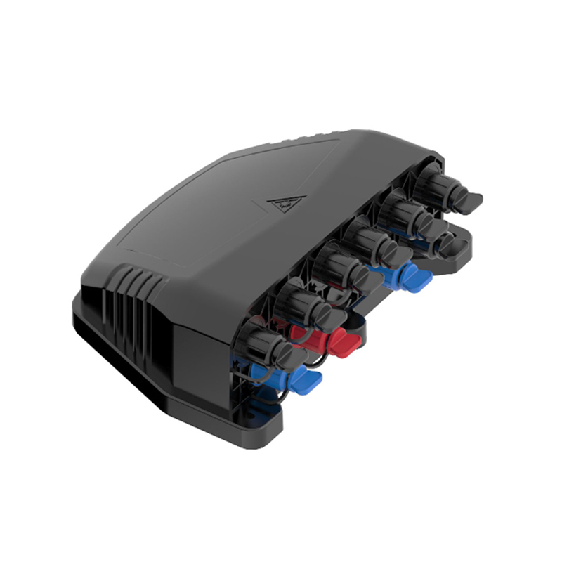
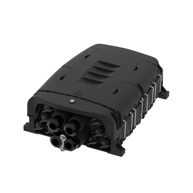
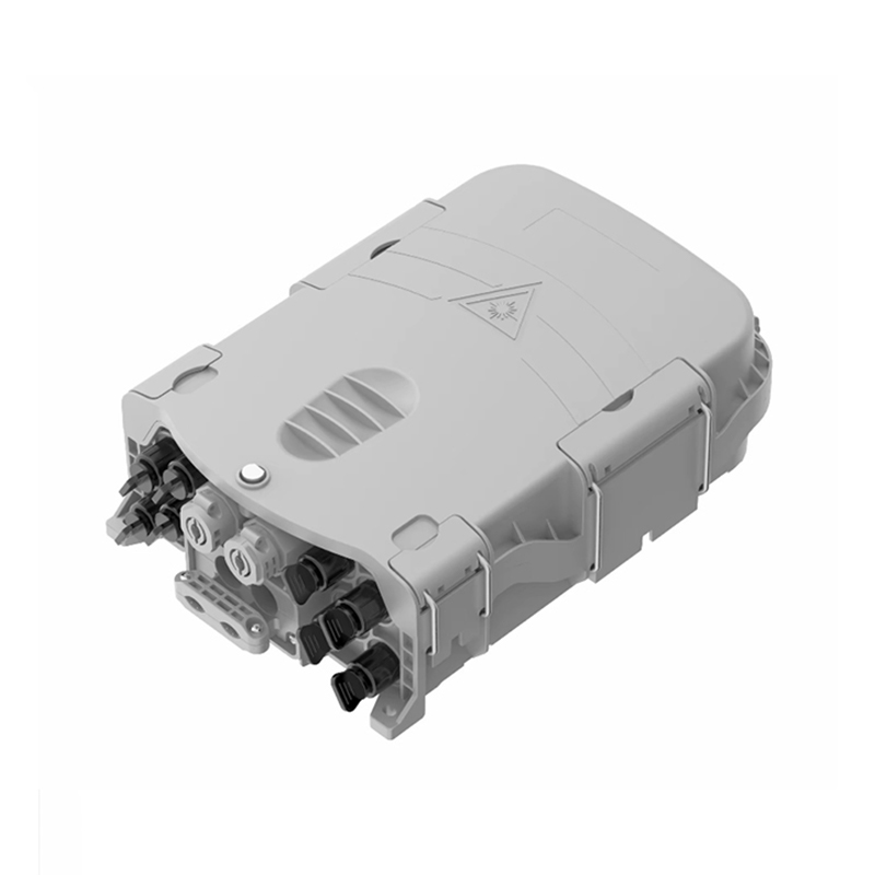
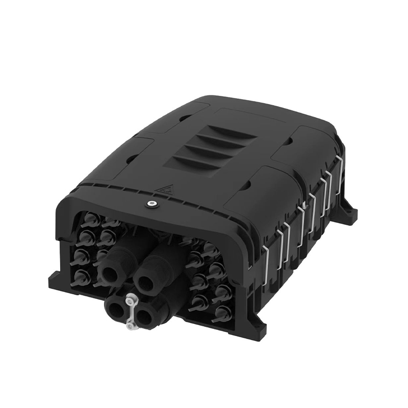
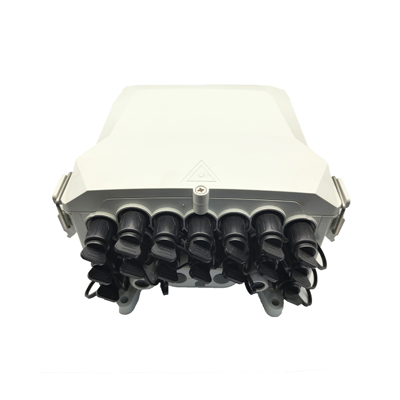
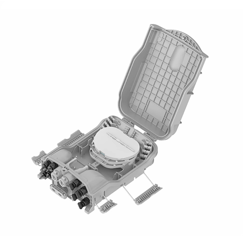 GSG08B Pre-connected Waterproof NAP Distribution BoxA weatherproof fiber management hub with pre-connected ports, this box simplifies drop cable routing and reduces sharp bends in outdoor access networks, supporting reliable connections and easier maintenance.View Product →
Fiber Optic Cable Bending Radius FAQs
What is the general minimum bending radius for fiber optic cable?
The general minimum is 10 times the cable outer diameter for installed cable and 20 times the outer diameter while pulling. Always refer to the manufacturer's datasheet for exact values.
What happens if you bend fiber optic cable too much?
Too much bending causes macrobending loss, visible attenuation spikes on an OTDR, and can eventually lead to fiber breakage due to stress corrosion.
What is the difference between bend radius and bend diameter?
Bend diameter is twice the bend radius. A radius of 50 mm corresponds to a diameter of 100 mm, meaning the cable would fit in a circle with that diameter.
Are bend-insensitive fibers able to bend tighter?
Yes, G.657 fibers are designed for tighter bending, but the cable jacket and strength members still impose a minimum radius. The fiber-level advantage matters when individual fibers are routed in trays or connectors.
How do I measure the cable outer diameter?
Use a caliper or micrometer across the jacket, measuring at the thickest point. Avoid measuring over printing or ribs. Then multiply by 10 or 20 to get the implied minimum radius.
The fiber optic cable bending radius is not an optional suggestion; it is a specification that directly affects attenuation and reliability. Use 10 x OD for static installations, 20 x OD for pulling, and verify the datasheet for your specific cable. A few extra centimeters of radius at every corner will save hours of troubleshooting later.
If you need help selecting a cable or checking a bend limit for an upcoming project, talk to our engineering team. For a broader review of cable types and their characteristics, you can read an introduction to fiber optic cables on our news page.