English
 Español

 Inquiry
Fiber connectorization is the process of terminating a bare optical fiber with a connector so the fiber can be connected, disconnected, and reconnected through an adapter. It is the right solution whenever a fiber link needs a demountable interface: patch panels, distribution boxes, customer premises, splicing closures, and restoration points. Done correctly, connectorization gives a stable, low-loss connection; done badly, it becomes the first part of the link that fails inspection.
This guide covers connectorization vs. splicing, common connector types, field termination methods, quality limits, and what to look for when buying connectorized components.
Content
- 1 Connectorization vs. Splicing: Which Should You Choose?
- 2 Common Fiber Optic Connector Types in Connectorization
- 3 Field-Installable Connectorization Methods
- 4 Basic Steps for Fiber Connectorization in the Field
- 5 Connectorization Quality: Loss Limits and Testing
- 6 Pre-Connectorized and Waterproof Options for Outside Plant
- 7 Final Suggestion: Choose the Termination Strategy by Job Type
- 8 Fiber Connectorization FAQ
Connectorization vs. Splicing: Which Should You Choose?
Choose connectorization when you need a reusable, pluggable interface; choose splicing when the joint will stay permanent and must have the lowest possible loss. Connectorization is faster to install and easier to reconnect later, but it adds a small amount of insertion loss and depends on connector quality and cleanliness.
Splicing, especially fusion splicing, gives a permanent joint with very low attenuation. It is the standard method for trunk cables and long outside-plant links. For drop cables, patch cords, or any point that may need future reconfiguration, connectorization is usually the better operational choice.
| Comparison | Connectorization | Splicing |
|---|---|---|
| Nature of connection | Demountable connector and adapter | Permanent joint |
| Typical insertion loss | 0.2–0.5 dB | 0.02–0.1 dB for fusion splicing |
| Reconfiguration | Easy | Difficult |
| Equipment needed | Connector kit, cleaver, inspection scope | Fusion splicer or mechanical splice tool |
| Best use | Drops, patch panels, ODN termination | Long spans, high-fiber-count closures |
Common Fiber Optic Connector Types in Connectorization
SC and LC are the safest choices for most modern networks; FC, ST, and MPO remain useful for specific environments. The connector type must match the cable type, the equipment port, and the network density.
SC, LC, FC, ST, and MPO Connectors
SC and LC connectors dominate enterprise and telecom installations. SC uses a 2.5 mm ferrule and gives good mechanical stability; LC uses a 1.25 mm ferrule and is the preferred choice for high-density switches and patch panels. FC connectors have a threaded coupling that resists vibration and are often used in test equipment and industrial environments. ST connectors are common in legacy LAN and security systems. MPO connectors support multiple fibers in one ferrule and are used in high-density data-center trunks.
| Type | Ferrule Size | Typical Use |
|---|---|---|
| SC | 2.5 mm | Enterprise, FTTH, patch panels |
| LC | 1.25 mm | High-density data center and switching |
| FC | 2.5 mm | Test equipment, industrial, vibration-prone areas |
| ST | 2.5 mm | Legacy LAN and security networks |
| MPO | Multi-fiber | High-density backbone and parallel optics |
Another key choice is endface polish. For single-mode systems, use APC when the link carries RF video, GPON, or other reflectance-sensitive services; use UPC for most enterprise data links. The basic fiber optic cable construction rules also matter because connectors are ordered by cable outer diameter, fiber mode, and polish type.
Field-Installable Connectorization Methods
Field-installable connectorization is the right method for FTTH drops, emergency restoration, and small jobs where carrying a fusion splicer is impractical. It allows a technician to terminate a cable on-site without an epoxy-and-polish lab.
Mechanical Fast Connectors
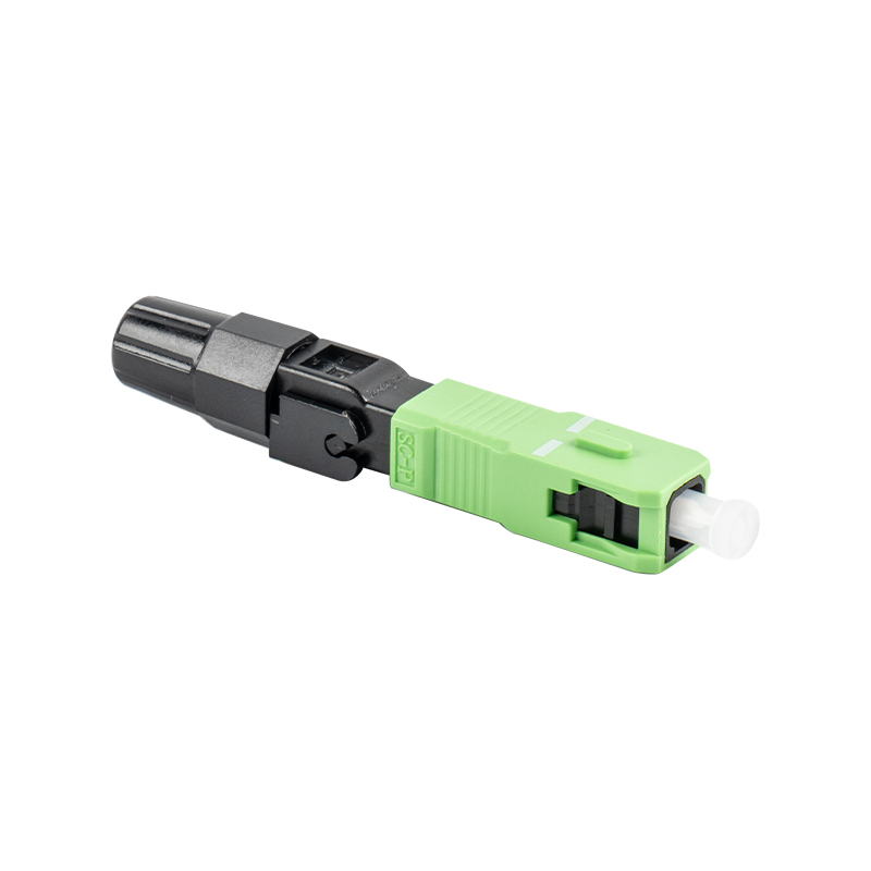
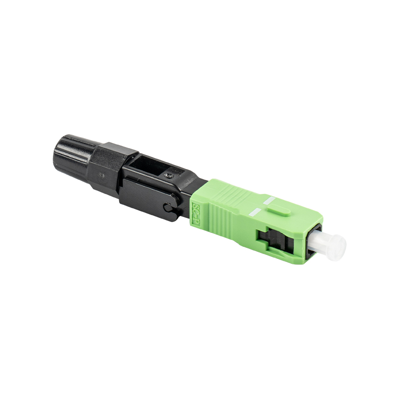
Mechanical fast connectors use an internal alignment mechanism and index-matching material to couple the field fiber to a short factory-polished stub fiber. They are fast, require no adhesive curing, and work well in clean, moderate-temperature environments. Their main limitation is sensitivity to contamination and extreme temperature changes.
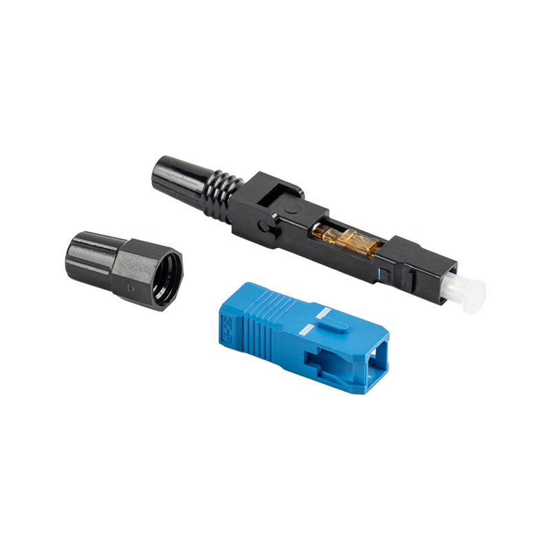 GSG-01-55mm-UPC Vertical Fiber Optic Fast connectorGSG-01-55mm-UPC Vertical Fiber Optic Fast connector adopts pre-polishing technology, which can quickly and tool-freely complete fiber optic termination on site. It can...View Product →
Hot-Melt Connectors
Hot-melt connectors have a factory-polished ferrule with adhesive preloaded in the connector body. The technician inserts the prepared fiber, heats the connector to melt the adhesive, and allows it to cool. This gives stronger strain relief and better temperature stability than many mechanical fast connectors, while still being field-installable.
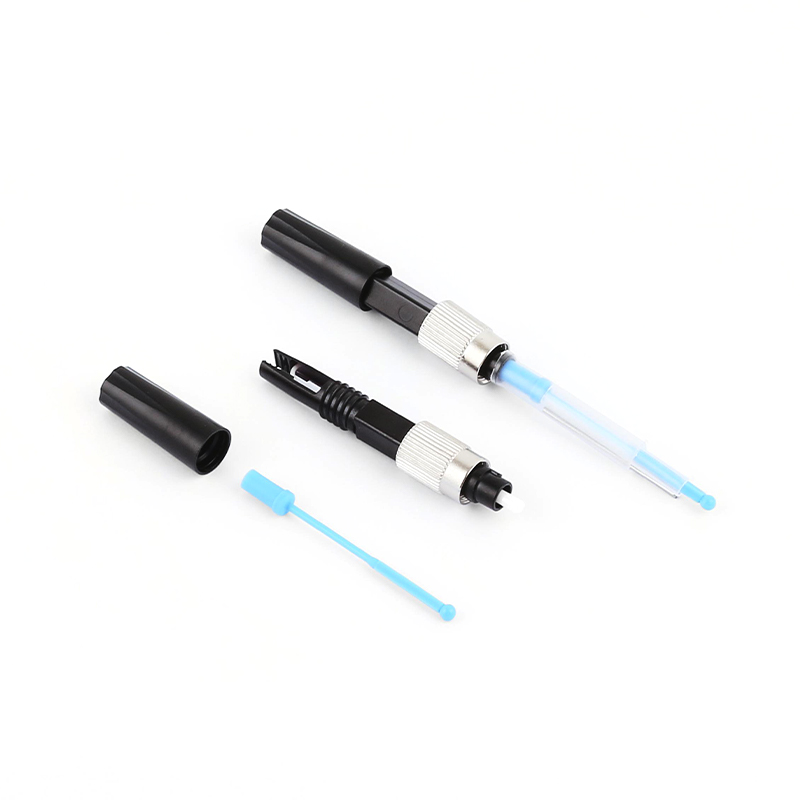 GSG-FC-55mm-UPC Fiber Optic Fast connectorGSG-FC-55 mm-UPC Fiber Optic Fast connector comes pre-polished, which means it is ready for use right out of the box. This eliminates the need for additional polishing...View Product →
What to Check Before Buying Field-Installable Connectors
- Cable outer diameter compatibility: 0.9 mm, 2.0 mm, or 3.0 mm
- Fiber mode: single-mode or multimode
- Endface polish: UPC or APC
- Insertion loss and return loss limits from the manufacturer
- Operating temperature range for outdoor use
Basic Steps for Fiber Connectorization in the Field
A repeatable field termination sequence prevents most connectorization failures: prepare the cable, strip the fiber, cleave accurately, assemble the connector, secure the fiber, inspect, and test.
- Strip the outer jacket and strength members to the length specified by the connector manufacturer.
- Remove the coating from the bare fiber without nicking the glass.
- Clean the bare fiber with lint-free wipes and optical-grade alcohol.
- Cleave the fiber at the required length and check the cleave angle.
- Insert the fiber into the connector until it seats against the internal stub fiber or ferrule.
- Fix the fiber using the appropriate method: crimp, heat cure, or splice.
- Inspect the endface with a fiber inspection scope before mating.
- Measure insertion loss and return loss with an OLTS or OTDR.
Most field failures come from contamination, wrong cleave length, poor fiber seating, or excessive cable strain. A small amount of training makes a large difference in rework rate.
Connectorization Quality: Loss Limits and Testing
For a field-installed single-mode connector, a practical acceptance range is insertion loss at or below 0.5 dB and return loss at or above 50 dB for UPC or 60 dB for APC. These values are common enough for commercial jobs and give a clear pass/fail decision when using an OLTS or OTDR.
If your project follows a formal performance standard, use the limits defined by that document. Many manufacturers reference IEC 61753-1 as the general performance guideline, but the simplest working rule is still: clean, inspect, and test every termination.
| Parameter | Target | Action if Exceeded |
|---|---|---|
| Insertion loss | ≤0.3–0.5 dB | Clean, reseat, then re-terminate |
| Return loss for UPC | ≥50 dB | Inspect and clean the endface |
| Return loss for APC | ≥60 dB | Inspect and clean the endface |
| Endface contamination | No visible particles | Clean, then retest |
Pre-Connectorized and Waterproof Options for Outside Plant
For outside plant and FTTH, factory pre-connectorized assemblies are the fastest and most repeatable connectorization strategy because they move polishing and testing out of the field. They also reduce the number of tools and skilled labor hours required on site.
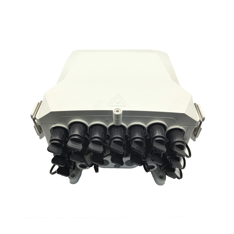
Pre-connectorized ODN solutions combine waterproof boxes, waterproof patch cords, and waterproof connectors so drop cables can be plugged in without fusion splicing. This approach shortens installation time and gives more consistent quality, but it requires accurate cable length planning before the product is ordered.
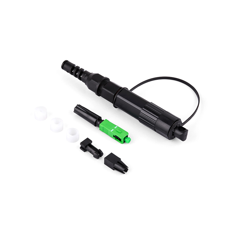
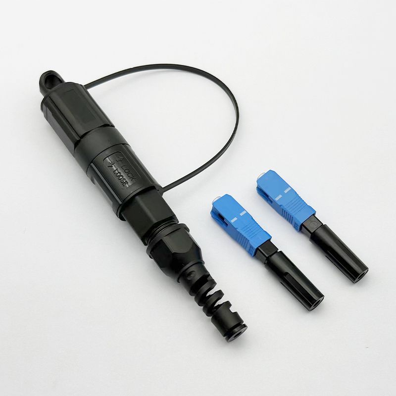 OptiTap SC-L02-UPC-Waterproof Fast connectorOPTITAP-SC-L02-UPC quick connect waterproof joint supports the construction needs of the next-generation ODN network, provides operators with high-performance, low-cos...View Product →
When a field-installed connector must survive rain, humidity, or temperature cycling, use a waterproof connector designed for outdoor exposure. It is usually safer to buy a tested pre-connectorized assembly than to terminate a cable from a bucket truck in poor light.
Because connector and cable compatibility is critical, ask the manufacturer for a matching connectorization kit before ordering in volume.
Final Suggestion: Choose the Termination Strategy by Job Type
Use fusion splicing for permanent high-fiber-count joints, use field-installable connectorization for drops and restorations, and use factory pre-connectorized assemblies for repeatable outside-plant deployments. The best strategy balances speed, loss, rework risk, and the skill of the installation crew.
Whatever method you choose, inspect every endface, record loss values, keep spare connectors in the kit, and verify that the connector fits the actual cable jacket before starting the job.
Fiber Connectorization FAQ
Is connectorization the same as splicing?
No. Connectorization creates a demountable termination, while splicing creates a permanent joint between two fibers.
What is the difference between a mechanical fast connector and a hot-melt connector?
A mechanical fast connector uses an internal alignment mechanism and index-matching material; a hot-melt connector uses preloaded adhesive and a factory-polished ferrule for stronger strain relief.
What insertion loss should I expect from a field-installed connector?
A good field-installed connector should stay below 0.5 dB; many achieve 0.2–0.3 dB when the cleave, insertion, and assembly steps are done correctly.
Can I reuse a field-installed connector?
Most field-installed connectors are not designed for reuse after final assembly. Re-terminate the fiber instead of reusing a connector that has been cured or crimped.
Why does my connector show intermittent loss?
The most common causes are contamination on the endface, poor fiber seating, an incompatible cable diameter, or excessive strain on the connector.